High-sensitivity MEMS piezoelectric microphone

A high-sensitivity, piezoelectric technology, applied in the field of microphones, can solve the problems of large energy loss, lack of microphone sensitivity, reduced microphone sensitivity, and signal-to-noise ratio, so as to reduce the influence of air damping, improve signal-to-noise ratio, and improve The effect of sensitivity

Active Publication Date: 2019-12-20
武汉敏声新技术有限公司
View PDF10 Cites 8 Cited by
  • Summary
  • Abstract
  • Description
  • Claims
  • Application Information

AI Technical Summary

Problems solved by technology

[0003] In the structure of the traditional beam-type piezoelectric microphone, the fixed end of the beam is set on the periphery of the vibration area, and the influence of air damping on the performance of the device is not fully considered in the design, thus reducing the sensitivity and signal-to-noise ratio of the microphone
Patent CN201811650376 discloses a microphone, but the free end of the cantilever beam diaphragm in this disclosed technology fails to effectively maximize the absorption of sound wave energy, and the energy loss is large, resulting in a lack of sensitivity of this type of microphone; patent CN201821645803 discloses a Microphone, this disclosed technology utilizes the cover film connected together by the free ends of the cantilever to keep the synchronous vibration of each cantilever to ensure the stability of the microphone signal output, but the amplitude of the cantilever cannot be maximized, reducing the sensitivity of the microphone

Method used


Image

  • High-sensitivity MEMS piezoelectric microphone
  • High-sensitivity MEMS piezoelectric microphone
  • High-sensitivity MEMS piezoelectric microphone

Examples


Embodiment Construction

[0023] The present invention will be further described below in conjunction with accompanying drawing and specific embodiment:

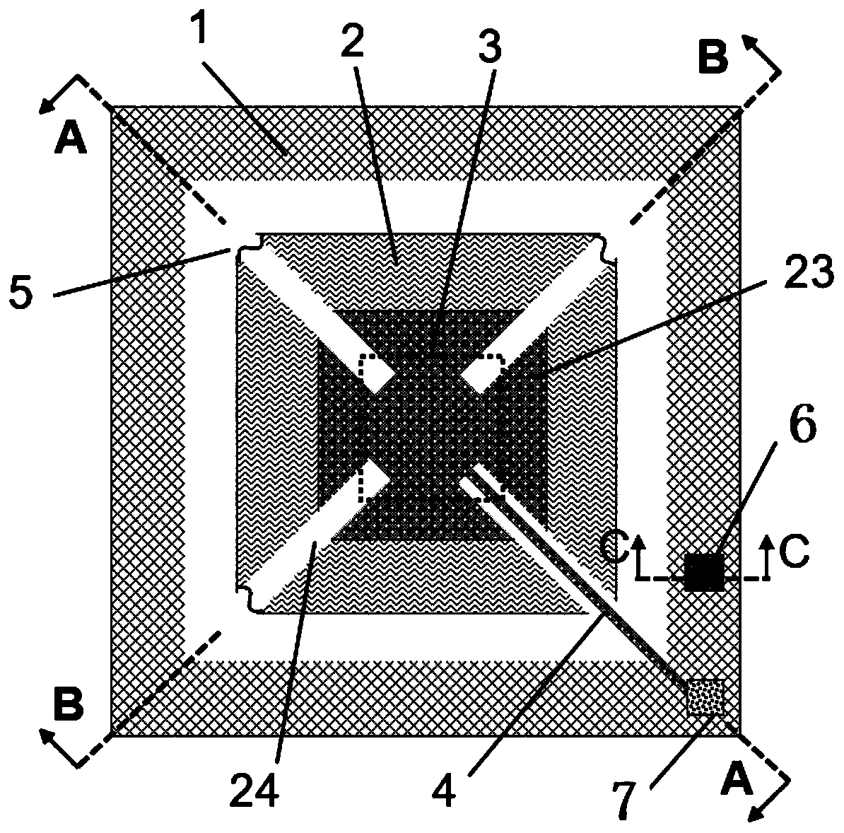
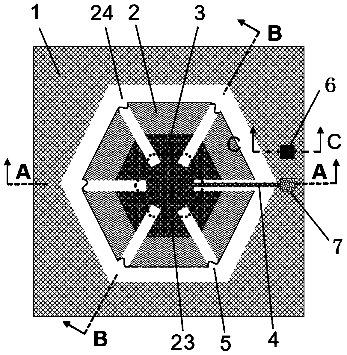
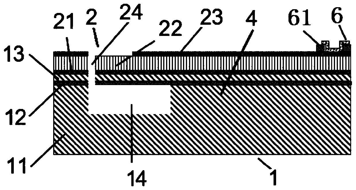
[0024] Such as Figure 1 to Figure 5 As shown, a high-sensitivity MEMS piezoelectric microphone includes a wafer substrate with a cavity 14 and a plurality of cantilever beams with a piezoelectric stack structure, and the cantilever beam includes a fixed end and is suspended in the cavity 14 Above the free end, the cantilever beam is a structure with one end narrow and the other end wide, wherein the narrower end is a fixed end; the center of the bottom surface of the cavity 14 is provided with a fixed column 3, and a plurality of cantilever beams are fixed. The ends are all connected to the top surface of the fixed column 3, gaps 24 are arranged between adjacent cantilever beams, and the free ends of adjacent cantilever beams are connected with flexible elastic parts 5 that can make the cantilever beams vibrate synchronously. , one of the gaps 24 i...


PUM


Abstract

A high-sensitivity MEMS piezoelectric microphone comprises a wafer substrate with a cavity and a plurality of cantilever beams with piezoelectric laminated structures, each cantilever beam comprises afixed end and a free end suspended above the cavity, each cantilever beam is of a structure with a narrow end and a wide end, and the narrower end of each cantilever beam is a fixed end; a fixed column is arranged in the center of the bottom surface of the cavity; the fixed ends of the multiple cantilever beams are connected to the top face of the fixed column, gaps are formed between the adjacent cantilever beams, the free ends of the adjacent cantilever beams are connected with flexible elastic pieces capable of enabling the cantilever beams to vibrate synchronously, and a connecting section used for leading out electric signals of the cantilever beams is arranged in one gap. By changing the structural form of the cantilever beams in the MEMS piezoelectric microphone, the sensitivity and the signal-to-noise ratio of the microphone are improved.

Description

technical field [0001] The invention relates to the technical field of microphones, in particular to a high-sensitivity MEMS piezoelectric microphone. Background technique [0002] A microphone is a device that converts sound signals into electrical signals, and is widely used in devices such as microphones, mobile phones, PCs, and vehicle-mounted voice recognition. After long-term development, the current performance indicators of the microphone are more focused on intelligence, digitization and miniaturization. Nowadays, MEMS piezoelectric microphone technology is more and more closely integrated with aerospace, biomedicine, consumer electronics, information communication, and military industries, which puts forward higher requirements for the reliability and sensitivity of the microphone. At present, condenser microphones occupy the main market share, but piezoelectric microphones will be widely used in the field of aeroacoustics in the future due to their advantages of ...

Claims


Application Information

Patent Timeline
Patent Type & Authority Applications(China)
IPC IPC(8): H04R19/00H04R19/04
CPCH04R19/005H04R19/04H04R2201/003
Inventor 孙成亮胡博豪吴志鹏林炳辉朱伟王磊周禹
Owner 武汉敏声新技术有限公司
Why Eureka
Try Eureka