Drying equipment with grinding function for material conveying device

A conveying device and material technology, applied in the direction of dehydration/drying/thickened sludge treatment, etc., can solve the problems of uneven evaporation, leakage, increased heat loss, etc., and achieve the effect of enhancing evaporation efficiency, increasing evaporation area, and increasing evaporation efficiency

Pending Publication Date: 2019-12-24
AMCON FUJIAN ENVIRONMENT PROTECTION EQUIP CO LTD
View PDF3 Cites 11 Cited by
  • Summary
  • Abstract
  • Description
  • Claims
  • Application Information

AI Technical Summary

Problems solved by technology

[0004] This kind of drying equipment in the prior art has the following disadvantages: 1. The drying efficiency of mud cakes that cannot be molded with high moisture content is extremely low
2. After the mud cake falls to the mesh belt, it cannot be spread evenly in a short time, and it often accumulates together, and even blocks the ventilation mesh of the filter on the mesh belt, affecting the effect of ventilation and evaporation
3. During the conveying process, the shape of the mud cake will not change, the moisture inside the mud ball cannot be discharged, and the mud ball at the bottom cannot always be in contact with the hot air during a conveying process, resulting in uneven evaporation
4. The hot air rises vertically from the bottom, and there is no horizontal hot air. For the sludge on the mesh belt, the evaporation efficiency is not high
5. Since the discharge port is open, hot air will leak from the discharge port, increasing heat loss

Method used


Image

  • Drying equipment with grinding function for material conveying device
  • Drying equipment with grinding function for material conveying device
  • Drying equipment with grinding function for material conveying device

Examples


Embodiment Construction

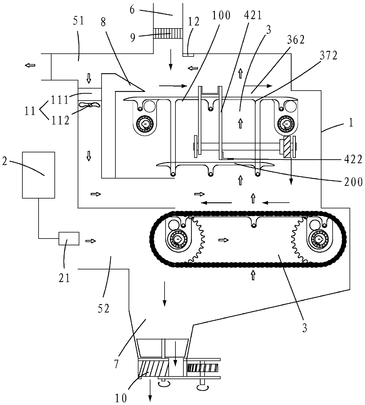
[0064] Such as figure 1 As shown, a drying equipment includes a drying chamber 1, a heating module 2, and a material conveying device 3 arranged in the drying chamber 1.

[0065] The drying chamber 1 is provided with a heat source inlet 51 , a heat source outlet 52 , a material inlet 6 , and a material outlet 7 .

[0066] The outlet point 21 of the heat supply module 2 is set at the heat source inlet 4 for providing heat source for the drying chamber 1 . The heat source module 2 is provided by a heat pump system.

[0067] The material conveying device 3 is arranged from top to bottom in the drying chamber 1, and two layers are arranged. The transport directions of the two material conveying devices 3 are opposite, that is, the materials are transported from the beginning of the material conveying device 3 on the upper layer to the end, then fall to the beginning of the material conveying device 3 on the next layer, and then are transported to the end, and then from the Outl...


PUM


Abstract

Drying equipment with a grinding function for a material conveying device comprises a heat supply module, a drying chamber and the material conveying device arranged in the drying chamber. The dryingchamber is provided with a heat source inlet, a heat source outlet, a feeding port and a discharging port. A heat outlet point of the heat supply module is arranged at the heat source inlet and used for providing a heat source for the drying chamber. The material conveying device is used for providing a platform for flatly laying materials and pushing the materials; the material conveying device is provided with a material grinding device, the material grinding device is driven by a first driving device to do reciprocating motion, and a certain angle is formed between the material grinding device and the pushing direction of the materials, so that the materials on the platform are ground, flattened, extruded, sheared and scraped. In the material conveying process, the grinding device carries out grinding, smoothing, extruding, shearing and scraping actions on materials on the platform, the evaporation area of the materials is increased, drying is carried out more efficiently, and the equipment is also suitable for the materials which are high in water content and cannot be formed.

Description

【Technical field】 [0001] The invention belongs to the technical field of material drying equipment, and specifically refers to a drying equipment of a material conveying device with a rolling function. 【Background technique】 [0002] Material drying equipment is widely used in the drying process of chemical, food, medicine, building materials and other industries. In the field of sludge treatment, the mud cake produced by the sludge dewatering machine falls freely to the mesh crawler belt after being granulated or slivered, and is transported by the multi-layer reciprocating mesh belt, and the mud cake on the mesh belt gradually evaporates. Finally, a material discharge with a lower moisture content is formed. [0003] Chinese invention patent 201810369116.0 discloses a return air circulation heating and drying device, and Chinese invention patent 201810953665.2 discloses a closed belt dryer. The material conveying devices in these two patent documents both use conveyor bel...

Claims


Application Information

Patent Timeline
Patent Type & Authority Applications(China)
IPC IPC(8): C02F11/13
CPCC02F11/13
Inventor 郑朝志
Owner AMCON FUJIAN ENVIRONMENT PROTECTION EQUIP CO LTD
Why Eureka
Try Eureka