
Single-needle machine of chain-link fences

A chain-link fence, single-needle technology, applied in the directions of wire mesh, knitting, textiles and papermaking, can solve the problems of short life, slow rebound speed of positioning needles, and short service life.

Pending Publication Date: 2019-12-24
安平县宝川丝网制品有限公司
View PDF0 Cites 0 Cited by
  • Summary
  • Abstract
  • Description
  • Claims
  • Application Information

AI Technical Summary

Problems solved by technology

[0003] At present, most of the chain link fence machines on the market are "collision type", "collision type" Gu Mingsiyi, which drives the movement of the positioning needle through collision during the working process, the noise is relatively large, and its service life is short, such as Figure 7 As shown, the positioning pin of the existing chain link fence machine is a double-needle type, and the positioning function can only be realized by the two positioning pins acting alternately. Each positioning pin is connected by a connecting rod, and the middle part of the connecting rod is fixed on the rotating sleeve , the rotating sleeve is rotatably connected to the installation shaft, the other end of the connecting rod is provided with a bearing, and a collision block is provided above the bearing. The connecting rod reciprocates, when the bearing of the connecting rod collides with the collision block above
The connecting rod will rotate, and the positioning pin will be lifted. When the bearing passes the collision block, the connecting rod will return and the positioning pin will fall. Therefore, this kind of chain link fence machine is often called "collision type". Loud noise, and it is easy to cause damage to components, and the life is relatively short. In addition, because the bearing takes a certain time to pass, the positioning needle rebounds slowly, so it is necessary to use two needles to move alternately to realize the function.

Method used


Image

  • Single-needle machine of chain-link fences
  • Single-needle machine of chain-link fences
  • Single-needle machine of chain-link fences

Examples


Embodiment Construction

[0023] A specific embodiment of the present invention will be described in detail below in conjunction with the accompanying drawings, but it should be understood that the protection scope of the present invention is not limited by the specific embodiment.

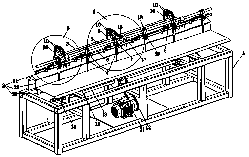
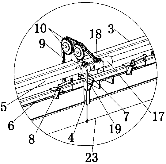
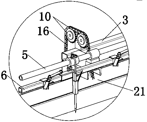
[0024] like Figure 1-6 As shown, a kind of single-needle chain link fence machine provided by the embodiment of the present invention includes a chassis 1, a driving mechanism, a main transmission mechanism, a netting mechanism and a turnover mechanism 2, and the netting mechanism includes a netting frame 3. The net frame 3 is slidably connected on the bottom frame 1, and the netting frame 3 is slidably connected on the bottom frame 1 by the guide rail 15, and can reciprocate relative to the bottom frame 1; the driving mechanism includes a drive motor 11, a main transmission chain 12 and The main rotating shaft 13, the drive motor 11 is fixed on the underframe 1, the two ends of the main rotating shaft 13 are fixed on the...


PUM


Abstract

The invention belongs to the technical field of chain-link fence machines, and particularly relates to a single-needle machine of chain-link fences which comprises an underframe, a driving mechanism,a main transmission mechanism, a mesh knitting mechanism and a turnover plate mechanism; the mesh knitting mechanism is slidably connected to the underframe and can reciprocate relative to the underframe; the mesh knitting mechanism comprises a knitting frame, a plurality of positioning needles, a rotating shaft and a first auxiliary transmission mechanism, the plurality of positioning needles arefixed on a fixing bar fixed on the knitting frame, each positioning needle is connected with the rotating shaft through a rope, the rotating shaft is rotatably connected to the knitting frame and isconnected with the driving mechanism through the first auxiliary transmission mechanism, and the rotating shaft is driven to rotate; original collision type transmission of the positioning needles ischanged into rope transmission, so that noise is reduced, components can be protected to a great extent, and the service life of each positioning needle is prolonged; the rebound speed of the positioning needles is greatly also increased by adopting the rope transmission, and therefore, one positioning needle can be used for replacing the original two positioning needles.

Description

technical field [0001] The invention belongs to the technical field of chain link fence machines, in particular to a single-needle chain link fence machine. Background technique [0002] Chain link fence machine is also known as diamond net machine, coal mine support net machine, anchor net machine, chain link fence machine product display machine, net weaving machine. Chain link fence machine is a kind of wire mesh machine that crochets low carbon steel wire, stainless steel wire, aluminum alloy wire, PVC wire and plastic sprayed wire to form chain link fence. The mesh has uniform mesh, smooth mesh surface and beautiful appearance , The web width is adjustable, the wire diameter is adjustable, it is not easy to corrode and has a long service life, the weaving is simple, beautiful and practical. [0003] At present, most of the chain link fence machines on the market are "collision type", "collision type" Gu Mingsiyi, which drives the movement of the positioning needle thro...

Claims


Application Information

Patent Timeline
IPC IPC(8): D04B33/00B21F27/02
CPCB21F27/02D04B33/00
Inventor 张文学赵树永马晨鹏王杭张天宇张天华
Owner 安平县宝川丝网制品有限公司
Learn More