
Pulse modulation signal carrier frequency measuring system and method

A technology of pulse modulation signal and carrier frequency, applied in the direction of frequency measurement device, etc., can solve the problems of affecting the accuracy of results, misjudgment of zero-crossing, affecting the accuracy of frequency results, etc., to simplify hardware design, design flexibility, and improve accuracy. Effect

Inactive Publication Date: 2019-12-24
上海微波技术研究所(中国电子科技集团公司第五十研究所)
View PDF5 Cites 5 Cited by
  • Summary
  • Abstract
  • Description
  • Claims
  • Application Information

AI Technical Summary

Problems solved by technology

[0004] 1) The use of hardware to implement frequency measurement algorithms requires the design of special hardware circuits, resulting in complex hardware circuit design, hardware circuits with certain specificity, and difficult to upgrade and improve;
[0005] 2) Conventional frequency measurement and cycle counting methods record the number of integer multiples of cycles, which affects the accuracy of the final calculated frequency results;
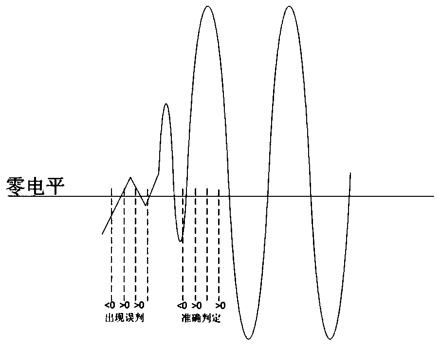
[0006] 3) The conventional zero-crossing judgment is not very flexible, and it is easily affected by factors such as noise and signal jitter. Misjudgment of zero-crossing occurs, thus affecting the accuracy of the results

Method used


Image

  • Pulse modulation signal carrier frequency measuring system and method
  • Pulse modulation signal carrier frequency measuring system and method
  • Pulse modulation signal carrier frequency measuring system and method

Examples


Embodiment Construction

[0041] The present invention will be described in detail below in conjunction with specific embodiments. The following examples will help those skilled in the art to further understand the present invention, but do not limit the present invention in any form. It should be noted that those skilled in the art can make several changes and improvements without departing from the concept of the present invention. These all belong to the protection scope of the present invention.

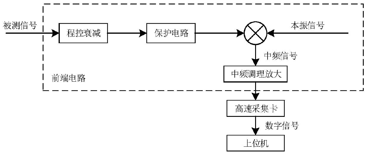
[0042] Such as Figure 1 to Figure 4 As shown, a pulse modulation signal carrier frequency measurement system and method provided by the present invention include a front-end circuit, a high-speed acquisition card and a host computer. The front-end circuit is used to mix the measured signal and the local carrier, and output pulse modulation The intermediate frequency carrier signal is sent to the high-speed acquisition card; the high-speed acquisition card is used to convert the collected pulse-modulate...


PUM


Abstract

The invention provides a pulse modulation signal carrier frequency measuring system. The system comprises a front-end circuit, a high-speed acquisition card and a host computer, the front-end circuitis used for performing frequency mixing on a tested signal and a local carrier and outputting a pulse modulation intermediate frequency carrier signal to the high-speed acquisition card, the high-speed acquisition card is used for converting the acquired modulation pulse intermediate frequency carrier signal to a digital signal and transmitting the digital signal to the host computer, and the hostcomputer is used for performing a frequency measuring algorithm based on zero passage judgment and cycle counting on the acquired digital signal. According to the system, the measurement of the carrier frequency of the pulse modulation signal is realized on the host computer so that the overall architecture of the device for realizing the algorithm is more software-based, the design thought of software radio is satisfied, the hardware design is simplified, the hardware architecture is more universal, the design of the software algorithm of the host computer is more flexible, and the influenceof signal jitter noise on a measuring result in a signal frequency measuring process is optimized; and the precision of frequency measurement is improved by employing a cycle measuring method, zero passage detection and linear interpolation.

Description

technical field [0001] The invention relates to the technical field of signal testing, in particular to a system and method for measuring the carrier frequency of a pulse modulation signal. Background technique [0002] Pulse modulation signal is a common signal form in electronic equipment such as radar communication, electronic countermeasures, and airborne transponders. Carrier frequency measurement of pulse modulated signals is a common function of signal test instruments. Common frequency measurement methods include frequency counting method, cycle measurement method, zero-crossing detection method, etc. These measurement methods are mainly implemented on hardware, and each measurement method has its own advantages and disadvantages. Directly applied to the measurement of the carrier frequency of the pulse modulation signal has the disadvantages of insufficient measurement accuracy and sensitivity to signal noise and jitter. [0003] Problems with prior art: [0004]...

Claims


Application Information

Patent Timeline
IPC IPC(8): G01R23/15
CPCG01R23/15
Inventor 樊光辉韩立群
Owner 上海微波技术研究所(中国电子科技集团公司第五十研究所)
Learn More