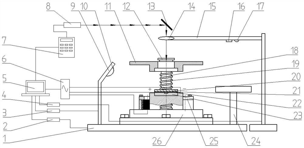
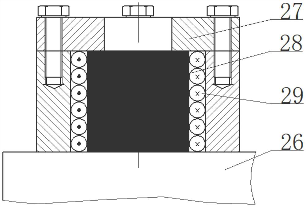
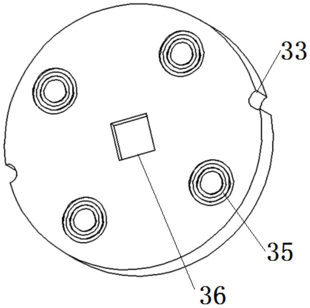
Quick-change pulse current processing and laser shock foil composite micro-forming device capable of automatic centering and adjustment of spot diameter and its application method

A technology of spot diameter and automatic centering, applied in laser welding equipment, manufacturing tools, welding equipment, etc., can solve the problems of complex pressing method, cumbersome disassembly process, long processing cycle interval, etc., and achieve the degree of dislocation entanglement. The effect of reducing and improving forming quality and high degree of automation

Active Publication Date: 2020-11-20
JIANGSU UNIV
View PDF2 Cites 0 Cited by
  • Summary
  • Abstract
  • Description
  • Claims
  • Application Information

AI Technical Summary

Problems solved by technology

However, this method only uses laser shock as a processing technology, and the pressing method is relatively complicated. It needs to rely on multiple bolts to connect and fix the clamping device. Therefore, the disassembly process after processing is relatively cumbersome, that is, two adjacent processing long cycle times

Method used


Image

  • Quick-change pulse current processing and laser shock foil composite micro-forming device capable of automatic centering and adjustment of spot diameter and its application method
  • Quick-change pulse current processing and laser shock foil composite micro-forming device capable of automatic centering and adjustment of spot diameter and its application method
  • Quick-change pulse current processing and laser shock foil composite micro-forming device capable of automatic centering and adjustment of spot diameter and its application method

Examples


Embodiment Construction

[0046] Embodiments of the present invention are described in detail below, examples of which are shown in the drawings, wherein the same or similar reference numerals designate the same or similar elements or elements having the same or similar functions throughout. The embodiments described below by referring to the figures are exemplary and are intended to explain the present invention and should not be construed as limiting the present invention.

[0047] In describing the present invention, it is to be understood that the terms "central", "longitudinal", "transverse", "length", "width", "thickness", "upper", "lower", "axial", The orientation or positional relationship indicated by "radial", "vertical", "horizontal", "inner", "outer", etc. is based on the orientation or positional relationship shown in the drawings, and is only for the convenience of describing the present invention and simplifying the description , rather than indicating or implying that the device or elem...


PUM


Abstract

The invention discloses a quick-change-type pulse current processing and laser shock foil composite microforming device capable of automatically centering and adjusting spot diameter and a method of the quick-change-type pulse current processing and laser shock foil composite microforming device, and relates to the technical field of advanced manufacturing micro-parts. The quick-change-type pulsecurrent processing and laser shock foil composite microforming device includes a laser emitting system, a space position adjustment system, a control system and a micro-part forming system. The methodcomprises the steps that first, a feature pattern set on a concave die is scanned by a three-dimensional camera, and the position of the feature pattern is compared with the position of a preset theoretical pattern to adjust the horizontal position of a three-dimensional mobile platform; then ultrasonic waves are emitted to an ultrasonic reflection platform and the total time of the whole processis calculated, the distance between the three-dimensional mobile platform and an adjustable-focus lens is calculated, then quick pressing of the device is realized by a magnetic suction device, and apulse current is applied to the two ends of foil; and finally, through pulse laser shock, impact force is generated by using explosion of plasma, and forming of the foil is realized, The accuracy ofa laser action point can be significantly improved, and the forming quality of the metal micro-parts is improved.

Description

technical field [0001] The invention relates to the technical field of advanced manufacturing micro-parts, in particular to a quick-change pulse current processing and laser shock foil composite micro-forming device capable of automatic centering and adjustment of spot diameter and a use method thereof. Background technique [0002] With the rapid development of today's productivity, especially in the field of aerospace and automobile manufacturing, the requirements for the strength and manufacturing accuracy of micro-parts with micro-features are also getting higher and higher, so a high-precision, high-quality micro-forming Process to ensure the precision of workpiece forming. Laser shock microforming is a processing method that uses laser energy as the shock source to instantly cause plastic deformation of the workpiece, which can form micro parts with better quality and higher precision. However, since the distribution form of the laser impact force is Gaussian spatial ...

Claims


Application Information

Patent Timeline
Patent Type & Authority Patents(China)
IPC IPC(8): B21D26/06B21D31/00
CPCB21D26/06B23K26/00
Inventor 张浩堃王霄顾鑫王科阳陆家鑫刘会霞
Owner JIANGSU UNIV
Why Eureka
Try Eureka