Protective device and protective method for ditch pass-through of shield tunneling machine in ultra-shallow earth covering region
A protective device and shield machine technology, which is applied in earthwork drilling, water conservancy projects, artificial waterways, etc., can solve problems such as potential safety hazards, impact on construction process, and surface uplift, etc., to achieve stable protection effect, simple structure, and protect the original status effect
- Summary
- Abstract
- Description
- Claims
- Application Information
AI Technical Summary
Problems solved by technology
Method used
Image
Examples
Embodiment 1
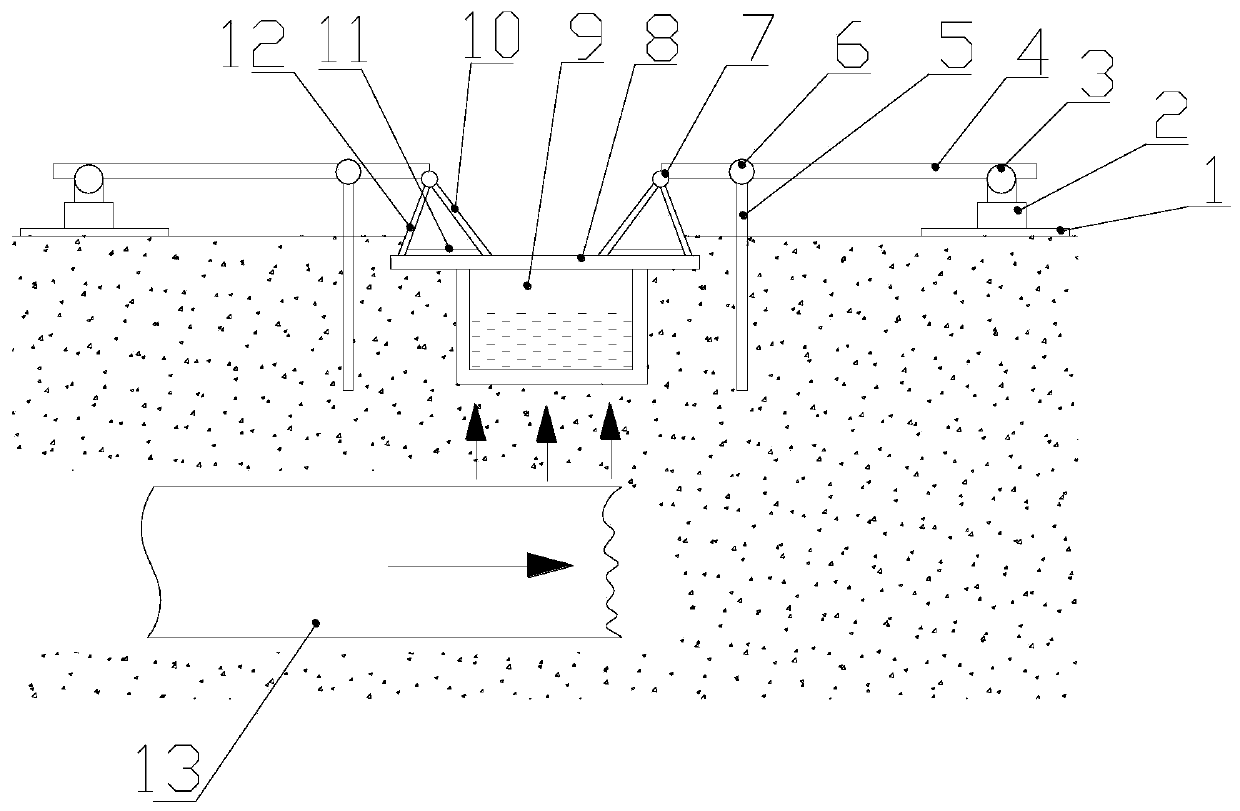
[0025] see figure 1 , the protection device provided by the present invention for a shield machine in an ultra-shallow soil-covered area to cross a ditch includes a cover plate 8 covering the ditch 9 and the substrate on both sides of the ditch 9, and a pressing mechanism and a pressing mechanism are symmetrically arranged at both ends of the cover plate 8 Connected power mechanism, the suppression mechanism includes suppression rod 4, ground anchor rod and tripod; one end of the suppression rod 4 is hinged with a tripod, and the bottom surface of the tripod is in contact with the upper surface of the cover plate 8, and the other end of the suppression rod 4 is hinged with a power mechanism And the fixed end of the bottom of the power mechanism is fixed on the ground substrate through the bottom plate 1, and the pressing rod 4 is parallel to the ground. The tripod structure is a triangular structure composed of the first support plate 10, the second support plate 11 and the thi...
Embodiment 2
[0027] The protection method of the protection device provided by the present invention is as follows: first, a cover plate 8 is arranged on the ditch 9, and the cover plate 8 covers the whole ditch and part of the base ground on both sides of the ditch, and the first branch is respectively set at both ends of the cover plate 8. Plate 10, the second support plate 11 and the third support plate 12 form a tripod mechanism with good stability, and the first support plate 10 and the third support plate 12 of the tripod are hinged and fixed to one end of the pressing rod 4 through the joint 7 At the same time, a fulcrum 6 is provided at one end close to the joint 7, and the pressing rod 4 can rotate at a certain angle along the fulcrum 6.
[0028] When it is detected that the shield machine 13 produces an upward destructive force during construction, start the power mechanism at this time, and jack up the other end of the pressing rod 4, so that one end of the pressing rod 4 will be...
Embodiment 3
[0031] The power mechanism provided by the invention is a pneumatic cylinder, a hydraulic cylinder or a moving push rod, which can generate upward thrust. During concrete implementation, the present invention adopts hydraulic cylinder 2, and the movable end of hydraulic cylinder 2 is hinged on the pressing bar 4, and the fixed end of hydraulic cylinder 2 is fixed on the ground through base plate 1, and the effect of base plate 1 is to support power mechanism better . When the shield machine crosses the ditch in the ultra-shallow drawing area, the upward centrifugal force generated by the head of the shield machine will damage the ditch in the ultra-shallow soil-covered area. At this time, the hydraulic cylinder 2 is turned on to move the mobile end upward. Under the action of the principle of leverage, the tripod at one end of the suppression rod generates a downward force under the action of the fulcrum of the ground anchor rod, which balances the upward destructive force of ...
PUM
 Abstract
Description
Claims
Application Information
 - R&D
- Intellectual Property
- Life Sciences
- Materials
- Tech Scout
- Unparalleled Data Quality
- Higher Quality Content
- 60% Fewer Hallucinations
Browse by: Latest US Patents, China's latest patents, Technical Efficacy Thesaurus, Application Domain, Technology Topic, Popular Technical Reports.
© 2025 PatSnap. All rights reserved.Legal|Privacy policy|Modern Slavery Act Transparency Statement|Sitemap|About US| Contact US: help@patsnap.com

