Dynamic characteristic analysis method of bearing-rotor system of high-speed motor of new energy automobile

A technology for new energy vehicles and high-speed motors, which is applied in the direction of mechanical bearing testing, mechanical component testing, machine/structural component testing, etc. It can solve the problem of inability to accurately predict the operating conditions of the bearing rotor system, less degrees of freedom, and inability to correctly establish Problems with rolling elements and raceways

Active Publication Date: 2019-12-27
WUHAN UNIV OF TECH
View PDF4 Cites 12 Cited by
  • Summary
  • Abstract
  • Description
  • Claims
  • Application Information

AI Technical Summary

Problems solved by technology

C.K.Babu et al. (C.K.Babu, N.Tandon, R.K.Pandey, Vibration modeling of a rigid rotor supported on the lubricated angular contact ball bearings considering six degrees of freedom and waviness on balls and races[J]. ASME J. Vib. Acoust. 2012, 134(1), p011006) established a six-degree-of-freedom dynamic model of the angular contact ball bearing rotor system, which considered the influence of friction torque on the system due to lubrication and contact loads, but did not consider the influence of high-speed centrifugal force
[0004] From the above literature search, it is found that the existing angular contact ball bearing rotor system dynamics model does not comprehensively consider the changes in the contact angle betw...

Method used


Image

  • Dynamic characteristic analysis method of bearing-rotor system of high-speed motor of new energy automobile
  • Dynamic characteristic analysis method of bearing-rotor system of high-speed motor of new energy automobile
  • Dynamic characteristic analysis method of bearing-rotor system of high-speed motor of new energy automobile

Examples


Embodiment Construction

[0074] In order to have a clearer understanding of the technical features, purposes and effects of the present invention, the specific implementation manners of the present invention will now be described in detail with reference to the accompanying drawings.

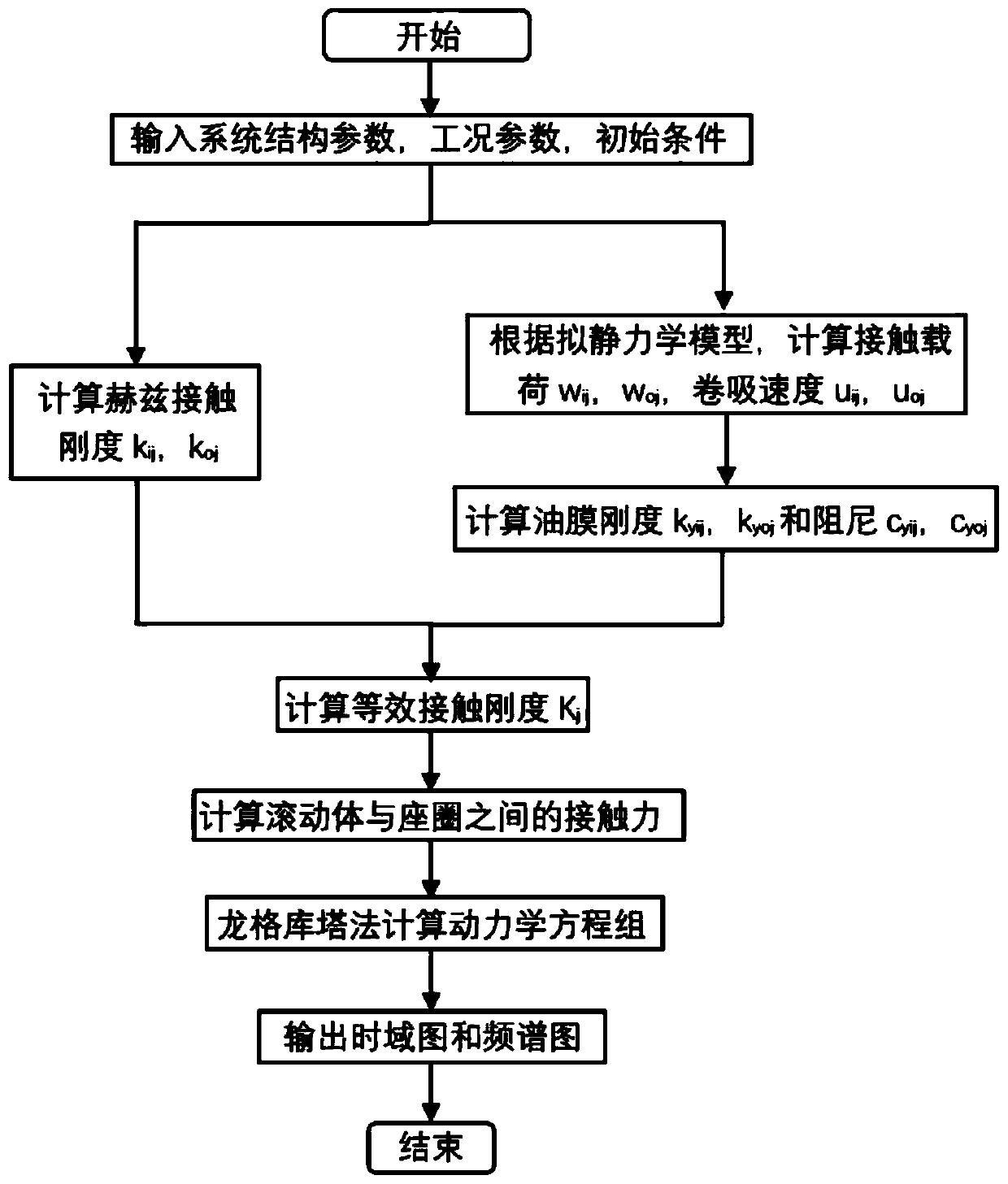
[0075] refer to figure 1 As shown, the present invention provides a new energy vehicle high-speed motor bearing-rotor system dynamic characteristic analysis method, comprising the following steps:

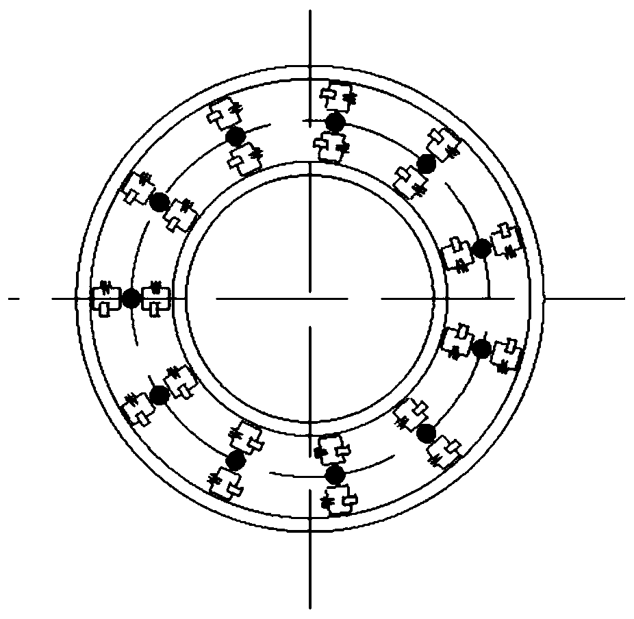
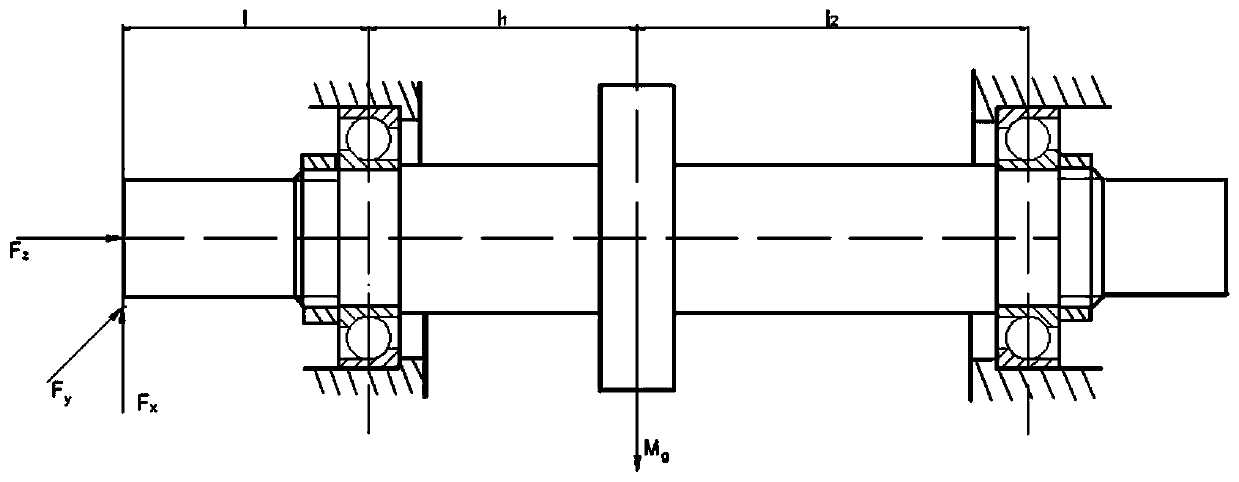
[0076] 1) According to the actual situation, the bearing is simplified to the mathematical model shown in Figure 2(a), and the bearing-rotor system is simplified to the mathematical model shown in Figure 2(b).

[0077] 2) Obtain the structural parameters, operating condition parameters and initial value conditions of the bearing rotor system. The structural parameters mainly include bearing parameters, material parameters, geometric parameters of the rotor, and the position parameters of the bearing and rotor. The operating ...


PUM


Abstract

The invention relates to a dynamic characteristic analysis method of a bearing-rotor system of a high-speed motor of a new energy automobile. The dynamic characteristic analysis method comprises the following steps of 1) acquiring a structural parameter, a working condition parameter and an initial value condition of the bearing rotor system, and building a model; 2) calculating an internal contact angle, an external contact angle and contact deformation by a high-rotational speed bearing quasi-static model; 3) respectively axial forces and radial forces of a left-side bearing and a right-sidebearing according to principles of torque balance and force balance, and solving an initial condition; 4) calculating a bearing entrainment speed and a contact load according to the internal contactangle, the external contact angle and the contact deformation; 5) calculating normal displacement quantity caused by consideration of vibration displacement between a left-side or right-side rolling body and a bearing sleeve ring and time-variable contact angle; 6) building six-degrees of freedom dynamic model of the bearing-rotor system; and 7) solving the bearing-rotor system by a variable-stepRunge-Kutta method, and simultaneously acquiring vibration response of the system. By the dynamic characteristic analysis method, the real-time operation condition of the bearing-rotor system can be accurately simulated, and meanwhile, the vibration response of the system is obtained.

Description

technical field [0001] The invention relates to the field of high-speed bearing-rotor, and more specifically, relates to a method for analyzing dynamic characteristics of a high-speed motor bearing-rotor system of a new energy vehicle. Background technique [0002] The bearing-rotor system composed of rolling bearings and rotors is widely used in high-speed motors of new energy vehicles, aero engines, machine tool spindles and other equipment. In order to accurately analyze the stability of the system at high speed and the law of the dynamic stability of the design parameters on the high speed bearing-rotor system. It is necessary to consider the change of oil film at high speed to establish a nonlinear dynamic model of high speed bearing-rotor system that is close to reality. [0003] It can be seen from the existing literature that the bearing-rotor system has been widely concerned by scholars at home and abroad. Zhang et al. (Zhang Y Y, Wang X L, Zhang X Q, et al.Dynami...

Claims


Application Information

Patent Timeline
IPC IPC(8): G01M13/00G01M13/04G01M13/045
CPCG01M13/00G01M13/04G01M13/045
Inventor 邓松郝丽娜华林钱东升韩星会
Owner WUHAN UNIV OF TECH
Why Eureka
Try Eureka