Microwave heating device and system

A microwave heating device and microwave heating technology are applied in the field of microwave applications to meet the requirements of application scenarios and realize the effect of volume

Pending Publication Date: 2019-12-27
成都亚彦科技有限公司
View PDF0 Cites 1 Cited by
  • Summary
  • Abstract
  • Description
  • Claims
  • Application Information

AI Technical Summary

Problems solved by technology

[0004] The embodiment of the present application provides a microwave heating device to solve or alleviate one or more technical problems in the prior art

Method used


Image

  • Microwave heating device and system
  • Microwave heating device and system
  • Microwave heating device and system

Examples


Embodiment Construction

[0022] In the following, only some exemplary embodiments are briefly described. As those skilled in the art would realize, the described embodiments may be modified in various different ways, all without departing from the spirit or scope of the present application. Accordingly, the drawings and descriptions are to be regarded as illustrative in nature and not restrictive.

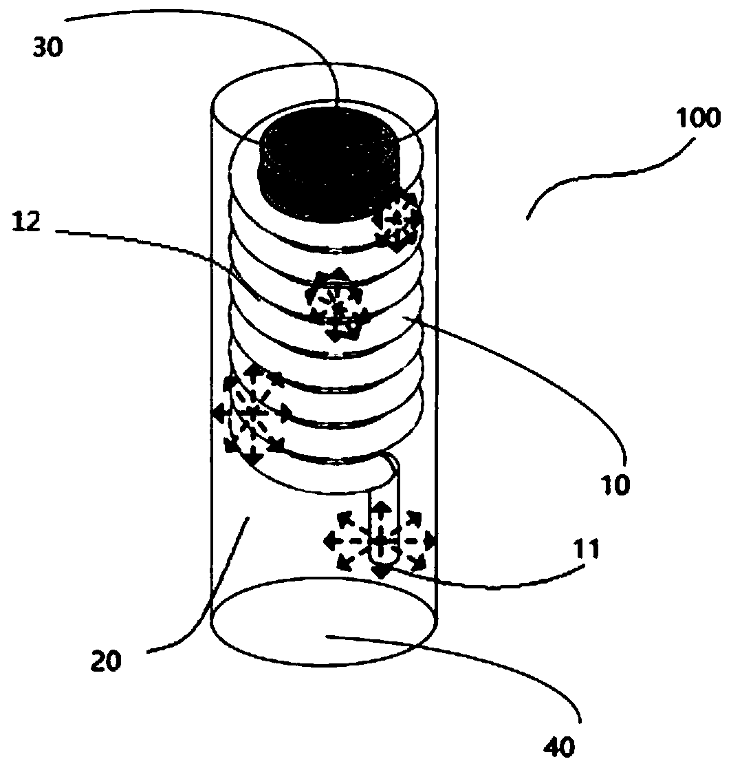
[0023] As an exemplary embodiment, figure 1 A schematic structural diagram of a microwave heating device according to an embodiment of the present application is shown. like figure 1 As shown, the microwave heating device includes a microwave transmission line 100 and a microwave feeding port (not shown in the figure). The microwave transmission line 100 includes a transmission conductor 10 , an auxiliary medium 20 and a transmission ground. The transmission ground is arranged around the transmission conductor 10 to form a shielding shell 40 . The auxiliary medium 20 and the transmission conductor 10 ar...


PUM


Abstract

The embodiments of the invention disclose a microwave heating device and system. The microwave heating device comprises a microwave transmission line and a microwave feed-in port; the microwave transmission line comprises a transmission conductor, an auxiliary dielectric and transmission ground; the transmission ground is arranged around the transmission conductor so as to form a shielding shell;and the auxiliary dielectric and the transmission conductor are arranged in the shielding shell; the transmission conductor comprises a first end; and the first end of the transmission conductor penetrates through the shielding shell; the microwave feed-in port is connected with the first end; the microwave feed-in port is used for introducing microwave signals; the shielding shell is used for carrying a to-be-heated object; and the microwave heating device is used for heating the to-be-heated object. According to the embodiments of the invention, the size of the device is miniaturized, and diversified application scene requirements are met.

Description

technical field [0001] The embodiments of the present application relate to the field of microwave application technology, and in particular to a microwave heating device and system. Background technique [0002] Compared with traditional heating methods, microwave heating greatly improves the utilization rate of energy, reduces energy loss, and has the advantages of high efficiency and environmental protection. Therefore, microwave heating has been widely used. [0003] Most microwave heating technologies in the prior art are based on coupling the antenna to the resonant cavity. The microwave signal is fed into the resonant cavity through the antenna, and resonance is realized in the resonant cavity, and the object to be heated in the resonant cavity moves back and forth at high frequency under the action of the electromagnetic field, thereby realizing heating. Since the resonance frequency is closely related to the size of the cavity, it is difficult to achieve resonance...

Claims


Application Information

Patent Timeline
IPC IPC(8): H05B6/64H05B6/70H05B6/76
CPCH05B6/64H05B6/70H05B6/76
Inventor 贾小翠林先其刘东屹
Owner 成都亚彦科技有限公司
Why Eureka
Try Eureka