Stirring device for solder paste for producing computer motherboard

A technology of a computer motherboard and a stirring device, which is applied in the computer field, can solve the problems of decreased work efficiency, dust entry, uneven stirring, etc., and achieves the effect of ensuring airtightness

Inactive Publication Date: 2019-12-31
HUNAN UNIV OF SCI & ENG
View PDF6 Cites 0 Cited by
  • Summary
  • Abstract
  • Description
  • Claims
  • Application Information

AI Technical Summary

Problems solved by technology

[0003] However, when using the stirring device in practice, there are still some shortcomings. For example, in the existing device, because the solder paste is highly viscous, the stirring is not uniform during the stirring process, and it is easy to adhere to the inner wall of the stirring vessel, so that the work efficiency is reduced. At the same time It will also make it inconvenient to clean the stirring vessel, because most of the carriers are not sealed when the solder paste is stirred, which makes the solder paste spill out during the stirring process, and there will be dust during the stirring process access to the interior of the carrier, allowing the production process to drop

Method used


Image

  • Stirring device for solder paste for producing computer motherboard
  • Stirring device for solder paste for producing computer motherboard
  • Stirring device for solder paste for producing computer motherboard

Examples


Embodiment 1

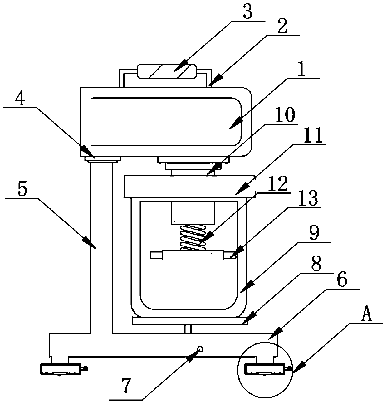
[0030] as attached Figure 1-8 The drive motor 1 shown is included, the top of the drive motor 1 is fixedly installed with a tie rod 2, the middle part of the pull rod 2 is fixedly installed with an anti-skid block 3, the left bottom of the drive motor 1 is fixedly installed with a fixed block 4, and the bottom of the fixed block 4 is fixed. Support bar 5 is installed, and the bottom of support bar 5 is fixedly installed with bottom support bar 6, and the middle part of bottom support bar 6 is movably installed with adjusting buckle 7, and the top of bottom support bar 6 is fixedly connected with movable plate 8, and the top of movable plate 8 The carrier 9 is inlaid and installed, and the left bottom of the driving motor 1 is disassembled and installed with a rotating shaft 10. The bottom of the rotating shaft 10 is movably connected with a sealing plate 11, and the bottom of the rotating shaft 10 is fixedly connected with a spring 12. The bottom of the spring 12 is fixedly co...

Embodiment 2

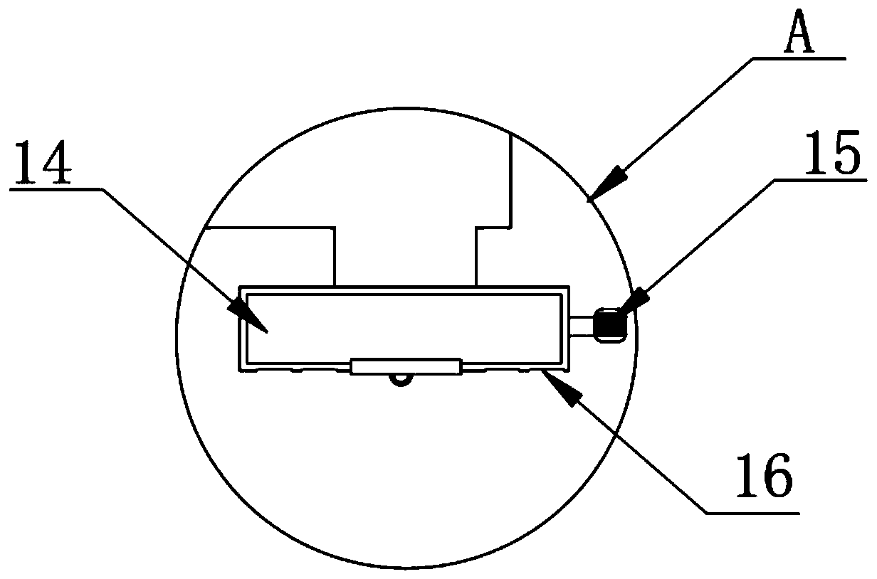
[0044] Specifically compared with Embodiment 1: the bottom of the movable block 14 is provided with a groove 16, and rubber blocks are fixedly installed inside the groove 16, and the number of rubber blocks and the number of grooves are several.

[0045] Using the above means: by fixing the rubber block inside the groove 16, the contact area with the ground can be increased, the friction force can be enhanced, and the damage to the machine can be reduced by the rubber block

[0046] working principle:

[0047] The first step: firstly install the parts of each part, and then put the solder paste into the inside of the carrier 9. At this time, using the carrier 9, the fixed block 92 fixedly installed at the bottom and the fixed groove 81 opened on the surface of the movable plate 8 are engaged. Then turn the gear 61 to the right, and because the left side of the gear 61 is meshed with the straight tooth 62, the straight tooth 62 moves upwards, so that the carrier 9 mounted on th...


PUM


Abstract

The invention discloses a stirring device for solder paste for producing a computer motherboard and particularly relates to the field of computers. The stirring device comprises a driving motor, wherein a draw bar is fixedly mounted at the top of the driving motor, a non-slipping block is fixedly mounted at the middle part of the draw bar, a fixed block is fixedly mounted at the bottom of the leftside of the driving motor, a supporting rod is fixedly mounted at the bottom of the fixed block, a bottom supporting rod is fixedly mounted at the bottom of the supporting rod, an adjusting buckle ismovably mounted at the middle part of the bottom supporting rod, a movable plate is fixedly connected to the top of the bottom supporting rod, and a loader is mounted at the top of the movable platein an embedded manner. According to the stirring device, a sealing plate and a spring are arranged and used in a combined manner, a snapping block fixedly mounted at the bottom of the sealing plate and a snapping groove formed in the top of the loader can be in snapped connection, and the sealing plate can be fixed to the top of the loader; and when the sealing plate is fixed, internal solder paste can be prevented from sprinkling outside the loader during stirring, and meanwhile, external dust and impurities can be prevented from entering the loader.

Description

technical field [0001] The invention relates to the field of computer technology, more specifically, the invention relates to a solder paste stirring device for computer motherboard production. Background technique [0002] Also called solder paste, gray paste, solder paste is a new type of soldering material that emerged with SMT. It is a paste formed by mixing solder powder, flux, and other surfactants and thixotropic agents. The mixture is mainly used for soldering of electronic components such as PCB surface resistance, capacitors, and ICs in the SMT industry, and the stirring device. The mixing device is used in water treatment engineering. The dosing box is mainly used for stirring, dissolving, and storing various chemicals. A metering pump or a water injector adds the liquid medicine to each dosing point, which includes a solder paste stirring device for computer motherboard production, which includes a solder paste stirring device for computer motherboard production....

Claims


Application Information

Patent Timeline
Patent Type & Authority Applications(China)
IPC IPC(8): B01F11/00B01F15/00
CPCB01F31/44B01F2035/351B01F35/00
Inventor 谭明杨杰杨环俊徐晓尹向东谭道军刘小兵
Owner HUNAN UNIV OF SCI & ENG
Why Eureka
Try Eureka