
Metal additive manufacturing device oriented to weightless flight and vacuum working conditions

A technology for metal additive manufacturing and manufacturing equipment, which is used in manufacturing tools, additive processing, metal processing equipment, etc., and can solve problems such as the inability to simultaneously simulate metal additive manufacturing verification near the ground

Active Publication Date: 2019-12-31
CHONGQING INST OF GREEN & INTELLIGENT TECH CHINESE ACADEMY OF SCI
View PDF9 Cites 5 Cited by
  • Summary
  • Abstract
  • Description
  • Claims
  • Application Information

AI Technical Summary

Problems solved by technology

[0006] The invention provides a high-energy beam metal additive manufacturing device for weightless flight and vacuum working conditions, expands the existing space additive manufacturing test and research technical route, builds a near-earth space metal additive manufacturing verification platform, and solves the problem of carrying scientific satellites and Outside the space station, the near-Earth cannot simultaneously simulate space microgravity and vacuum environment for metal additive manufacturing verification bottlenecks

Method used


Image

  • Metal additive manufacturing device oriented to weightless flight and vacuum working conditions
  • Metal additive manufacturing device oriented to weightless flight and vacuum working conditions
  • Metal additive manufacturing device oriented to weightless flight and vacuum working conditions

Examples


Embodiment Construction

[0043] The following will clearly and completely describe the technical solutions in the embodiments of the present invention. Obviously, the described embodiments are only some of the embodiments of the present invention, not all of them. Based on the embodiments of the present invention, all other embodiments obtained by persons of ordinary skill in the art without creative efforts fall within the protection scope of the present invention.

[0044] It should be noted that all directional indications (such as up, down, left, right, front, back...) in the embodiments of the present invention are only used to explain the relationship between the components in a certain posture (as shown in the drawing). If the specific posture changes, the directional indication will also change accordingly.

[0045]In addition, in the present invention, descriptions such as "first", "second" and so on are used for description purposes only, and should not be understood as indicating or implyin...


PUM

PropertyMeasurementUnit
Diameteraaaaaaaaaa

Abstract

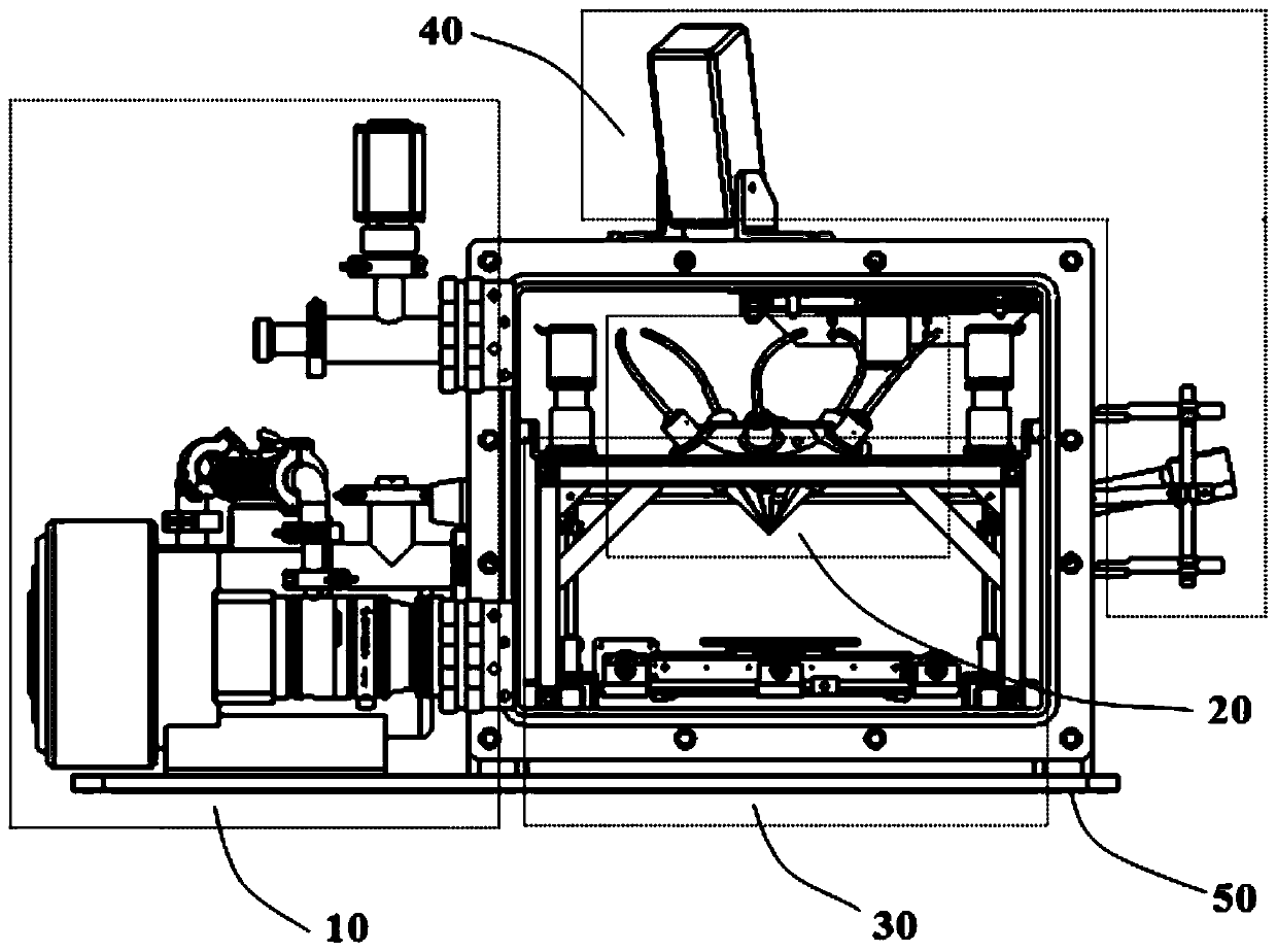
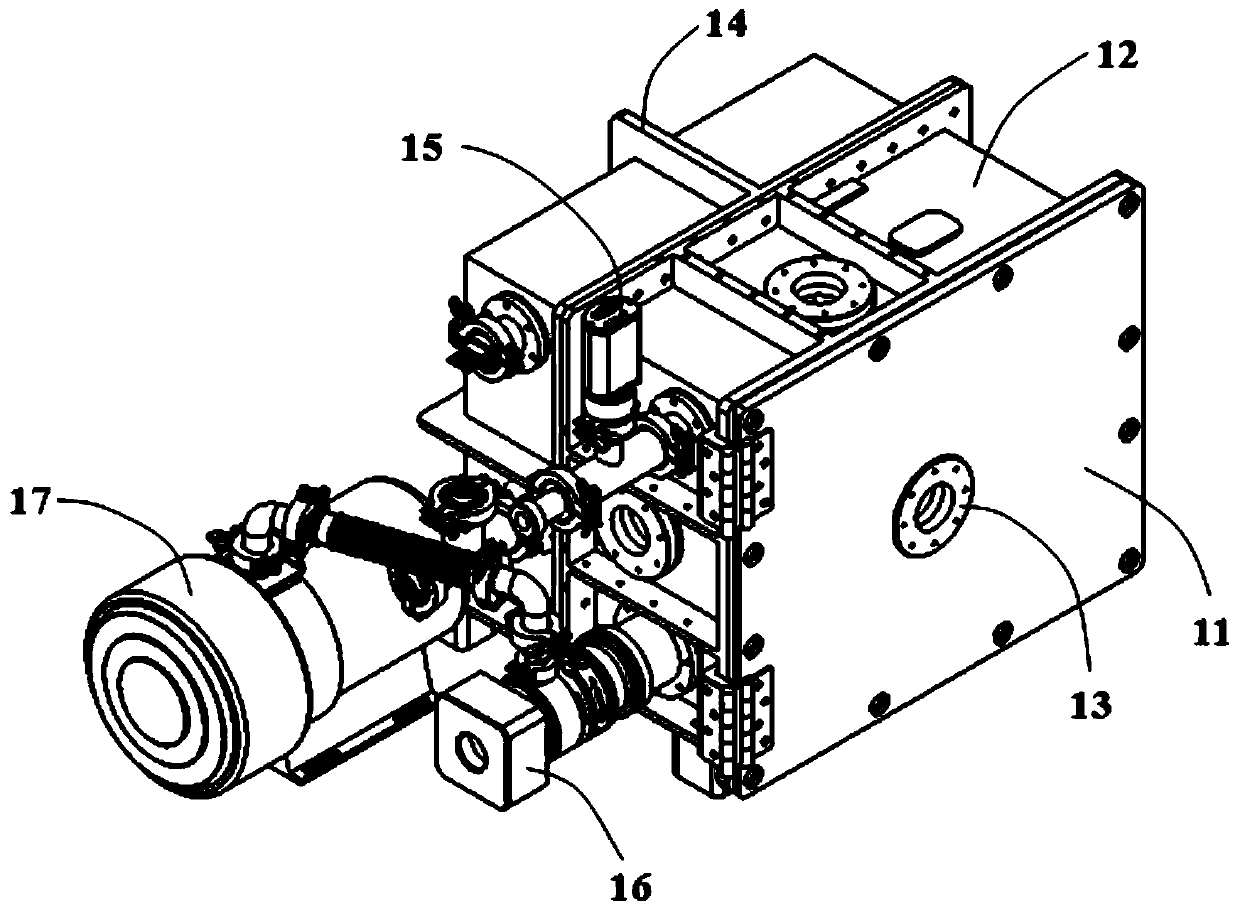
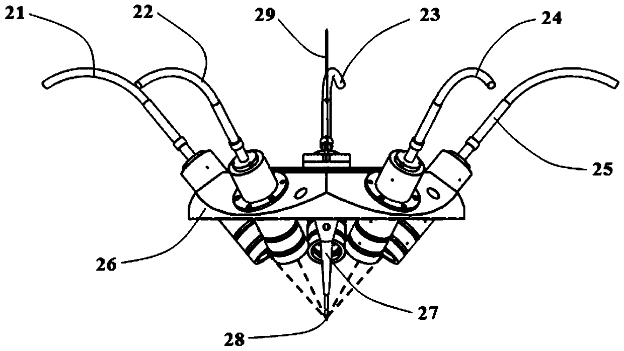
The invention discloses a metal additive manufacturing device oriented to weightless flight and vacuum working conditions. The metal additive manufacturing device comprises a vacuum system, a metal fusion system, a movement system and a monitoring system, metal wires are used as a raw preparation material, a high-energy-beam heat source is adopted as an energy source, and the device is used for metal additive precise manufacturing under weightless flight microgravity and vacuum working conditions. The design of a lightweight cavity and arrangement of the compact-type motion system are adopted,the ratio of an effective space of a molding area to the system occupation space is increased, weightless flight experiment platform mechanical and electrical constraint conditions are satisfied, andmetal additive manufacturing experiments in a weightless flight periodicity microgravity environment are carried out; an adjustable vacuum system is arranged to guarantee that the whole metal wire additive manufacturing process is carried out in a vacuum condition; the manufacturing process and state data are entirely recorded to provide a technical guarantee for the observation and traceback ofthe manufacturing process; the ring-column-type high-energy-beam heat source is adopted for focusing small-diameter light spots in cooperation with a precise wire feeding system, then it is guaranteedthat the heat source and the raw material are symmetric and concentric, and precise manufacturing is achieved.

Description

technical field [0001] The invention belongs to the interdisciplinary field of space manufacturing and material science, and relates to a metal additive manufacturing device for weightless flight and vacuum working conditions. Background technique [0002] In order to meet the supply guarantee in space exploration, reduce transportation pressure, reduce the number of spare parts, and respond to emergencies in a timely manner, while expanding the manufacturing technology of on-orbit components and helping the development of deep space exploration technology, the world is actively developing space additive manufacturing technology. This research will provide the key scientific basis and key technical basis for realizing the ready-to-use logistics support of the space station, and provide support for meeting the country's major strategic needs in the fields of aerospace, national defense and military industry. [0003] In view of the high vacuum, zero gravity and other external...

Claims


Application Information

Patent Timeline
IPC IPC(8): B23K26/342B23K26/12B23K26/70B23K26/03B23K15/00B23K15/06B33Y10/00B33Y30/00
CPCB23K26/342B23K26/1224B23K26/702B23K26/03B23K15/0086B23K15/06B33Y10/00B33Y30/00
Inventor 杨杰张祺马红林曹洪忠刘基权王国玉范树迁
Owner CHONGQING INST OF GREEN & INTELLIGENT TECH CHINESE ACADEMY OF SCI
Learn More