Preparation process of an explosion-proof magnetostrictive liquid level gauge

A magnetostrictive liquid level and preparation technology, which is applied in the direction of buoy liquid level indicators, etc., can solve the problems of the sharp increase in the cost of magnetostrictive liquid level gauges, the very high straightness requirements of waveguide wires, and the high cost of imported waveguide wires. , to achieve good insulation, high hardness, and reduce storage space and length requirements

Active Publication Date: 2021-09-03
XIAN ANCN INTELLIGENT INSTR
View PDF3 Cites 0 Cited by
  • Summary
  • Abstract
  • Description
  • Claims
  • Application Information

AI Technical Summary

Problems solved by technology

However, in the installation of its sensor, due to the limitation of the process method, only imported waveguide wire can be used for production, and the straightness of the waveguide wire is very high, and the waveguide wire must be stored in a straight line when storing
For the flexible liquid level gauge, its length is distributed between 4 meters and 20 meters, and the imported waveguide wire can only be stored in a straight line with a length of 20 meters, which takes up a lot of space; storage and transportation are very inconvenient, and the imported waveguide wire is expensive, which is domestic The price of the waveguide wire is more than 10 times, so that the cost of the magnetostrictive liquid level gauge increases sharply

Method used


Image

  • Preparation process of an explosion-proof magnetostrictive liquid level gauge
  • Preparation process of an explosion-proof magnetostrictive liquid level gauge
  • Preparation process of an explosion-proof magnetostrictive liquid level gauge

Examples


Embodiment Construction

[0028] Below in conjunction with accompanying drawing and embodiment the present invention is described in further detail:

[0029] The invention provides a preparation process of an explosion-proof magnetostrictive liquid level gauge, comprising the following steps,

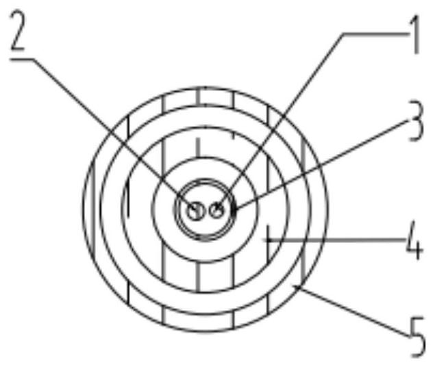
[0030] Step 1): Weld waveguide wire 1 and feeder 2, weld one end of waveguide wire 1 and feeder 2, and penetrate into inner protection tube 3 in parallel, and protect the welding spot of waveguide wire 1 and feeder 2 with a heat shrinkable tube;

[0031] Step 2): Insert the inner protective tube 3 into the bellows 4, and then insert the bellows 4 into the outer protective tube 5;

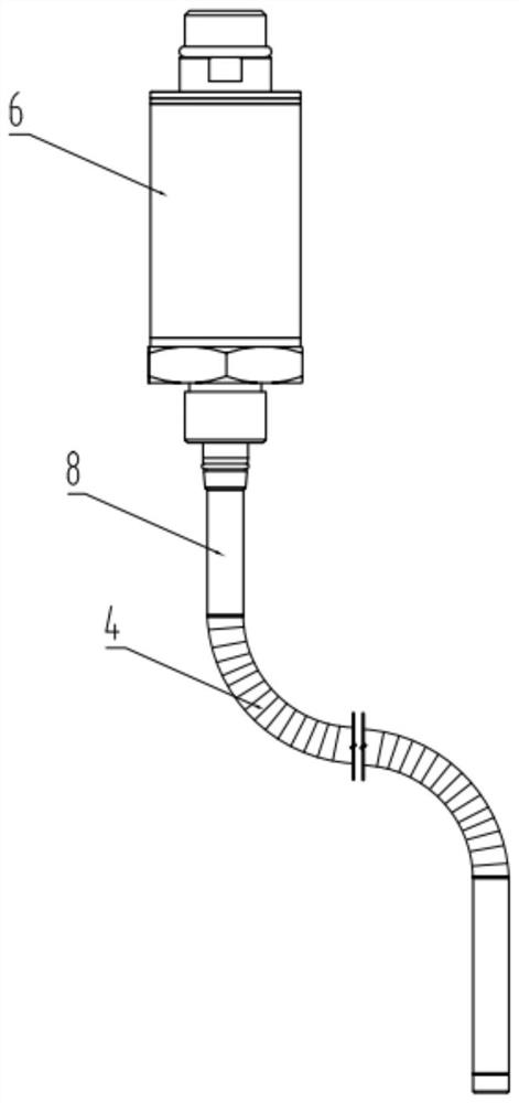
[0032] Step 3): The bellows 4 is welded to the steel pipe 8, and the inner protection tube 3 and the electronic compartment 6 are fixedly connected;

[0033] Step 4): the steel pipe 8 is welded to the electronic warehouse 6;

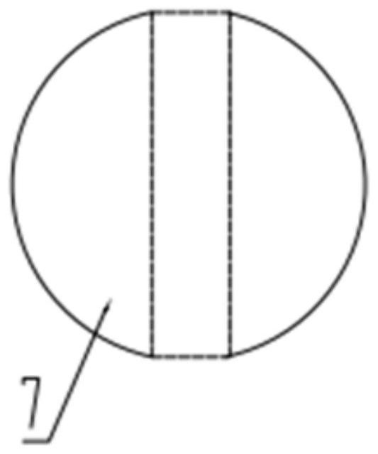
[0034] Step 5) The magnetic floating ball 7 is installed on the outside of the outer protection tube 5. The...


PUM

PropertyMeasurementUnit
diameteraaaaaaaaaa
thicknessaaaaaaaaaa
lengthaaaaaaaaaa

Abstract

The invention belongs to the technical field of liquid level measurement, and relates to a preparation process of an explosion-proof magnetostrictive liquid level gauge, including: welding waveguide wires and feeder wires, welding one end of the waveguide wires and feeder wires, using heat-shrinkable tubes for protection at solder joints, and parallel penetration into the inner protection tube; insert the inner protective tube into the corrugated tube, and thread the corrugated tube into the outer protective tube; the corrugated tube and the steel pipe are welded, and the inner protective tube and the electronic compartment are fixedly connected; the steel tube and the electronic compartment are welded; the magnetic floating ball is installed on the outside of the outer protective tube , the magnetic floating ball is spherical, the center of the magnetic floating ball is provided with a cylindrical through hole, and a magnet is installed inside the cylindrical through hole, the magnet is concentric with the cylindrical through hole, and the N pole of the magnet faces inward; The point protection method can effectively prevent the deformation of the waveguide wire at low temperature and the stress effect between the inner protection tubes; through the design of the installation structure and distribution of the magnets, each magnet is installed with the N pole facing inward to enhance the torsion of the waveguide wire The vibration amplitude of the wave increases the amplitude of the echo signal.

Description

technical field [0001] The invention belongs to the technical field of liquid level measurement, and relates to a preparation process of a liquid level gauge, in particular to a preparation process of an explosion-proof magnetostrictive liquid level gauge. Background technique [0002] In flammable and explosive environments such as oil and gas exploration and petrochemical industries, the measurement of the oil volume of oil tanks is mostly performed by manually climbing the tank and measuring with a ruler. Use a metric steel tape tape with a heavy hammer or a scale with a scale to measure, manually record the readings, manually look up the table for conversion, and finally get the oil quantity data. This measurement method is not only labor-intensive, but also has unsafe factors and cannot guarantee accuracy. [0003] There are several existing liquid level gauges, mainly including: ① capacitive type, diffused silicon pressure type liquid level gauge, this kind of sensor ...

Claims


Application Information

Patent Timeline
Patent Type & Authority Patents(China)
IPC IPC(8): B23P15/00G01F23/62
CPCB23P15/00G01F23/62
Inventor 王士兴官军昌
Owner XIAN ANCN INTELLIGENT INSTR
Why Eureka
Try Eureka