Optical imaging lens and imaging equipment

An optical imaging lens and lens technology, applied in optics, optical components, instruments, etc., can solve the problem of less cameras, and achieve the effect of correcting field curvature and astigmatism, good imaging effect, and increasing the amount of light passing through.

Active Publication Date: 2020-03-27
JIANGXI LIANCHUANG ELECTRONICS CO LTD
View PDF2 Cites 0 Cited by
  • Summary
  • Abstract
  • Description
  • Claims
  • Application Information

AI Technical Summary

Problems solved by technology

At present, chips with large target area and 8M high pixels used in the automotive field have begun to be popularized in the market, but there are still few cameras that can match them, especially the super-large aperture and telephoto automotive lenses.

Method used


Image

  • Optical imaging lens and imaging equipment
  • Optical imaging lens and imaging equipment
  • Optical imaging lens and imaging equipment

Examples


no. 1 example

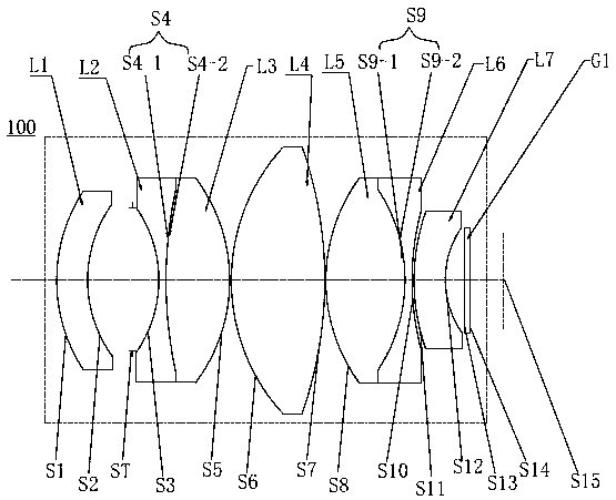
[0074] see figure 1 , the optical imaging lens 100 provided in this embodiment includes in sequence from the object side to the image side: a first lens L1, a stop ST, a second lens L2, a third lens L3, a fourth lens L4, a fifth lens L5, a Six lenses L6, a seventh lens L7 and a filter G1.

[0075] The first lens L1 has a negative refractive power, the object side S1 of the first lens is a convex surface, the image side S2 of the first lens is a concave surface, and the first lens L1 is a glass aspherical lens;

[0076] The second lens L2 has negative refractive power, and the object side S3 of the second lens and the image side S4-1 of the second lens are both concave surfaces;

[0077] The third lens L3 has positive refractive power, the object side S4-2 of the third lens, and the image side S5 of the third lens are both convex surfaces, the second lens L2 and the third lens L3 form a cemented body and both are glass spherical lenses, also That is, the image side S4-1 of th...

no. 2 example

[0091] For the structural schematic diagram of the optical imaging lens 200 provided in this embodiment, please refer to Figure 5 , the optical imaging lens 200 in this embodiment is roughly the same as the optical imaging lens 100 in the first embodiment, except that the first lens L1 has positive refractive power, and the curvature radius and material selection of each lens are different.

[0092] Table 3 shows relevant parameters of each lens in the optical imaging lens 200 provided in this embodiment.

[0093] table 3

[0094]

[0095] In addition, the parameters of each aspheric lens in this embodiment are shown in Table 4.

[0096] Table 4

[0097]

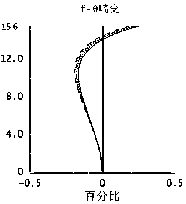
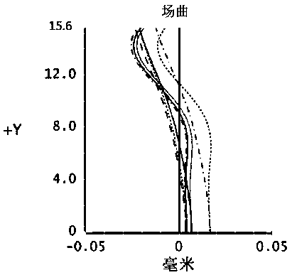
[0098] In this embodiment, its distortion, curvature of field and axial aberration curves are shown as Figure 6 , Figure 7 and Figure 8 shown by Figure 6 , Figure 7 and Figure 8 It can be seen that distortion, field curvature and axial aberration can all be well corrected in this embodiment.

no. 3 example

[0100] For the structural diagram of the optical imaging lens 300 provided by the third embodiment of the present invention, please refer to Figure 9 , the structure of the optical imaging lens 300 in this embodiment is roughly the same as that of the optical imaging lens 100 in the first embodiment, except that the first lens L1 is a glass spherical lens with positive refractive power, the second lens L2 and The third lens L3 is an independent lens (the two do not form a cemented body), and the curvature radius and material selection of each lens are different.

[0101] The relevant parameters of each lens in the optical imaging lens 300 provided in this embodiment are shown in Table 5.

[0102] table 5

[0103]

[0104] The parameters of each aspheric lens in this embodiment are shown in Table 6.

[0105] table 6

[0106]

[0107] In this embodiment, its distortion, curvature of field and axial aberration curves are shown as Figure 10 , Figure 11 and Figure 12 ...


PUM


Abstract

The invention provides an optical imaging lens and an imaging device, which sequentially include from the object side to the image side: a first lens with optical power, whose object side is convex and the image side is concave; a second lens with negative power , the object side is concave and the image side is concave; the third lens with positive refractive power is convex on the object side and the image side is convex; the fourth lens with positive refractive power is convex on the object side and the image side is Convex; the fifth lens with positive refractive power, the object side is convex, the image side is convex; the sixth lens with negative power, the object side is concave, the image side is concave, and the fifth lens and the sixth lens The lenses comprise a cemented body; a seventh lens with negative refractive power, whose object side is convex and its image side is concave; and a diaphragm. The optical imaging lens of the present invention has the characteristics of large aperture, long focal length, high resolution, etc., and can meet the requirements of the vehicle field for a lens with a small field of view and a high resolution.

Description

technical field [0001] The invention relates to the technical field of lens imaging, in particular to an optical imaging lens and imaging equipment. Background technique [0002] Advanced Driving Assistant System (ADAS for short) uses various sensors installed on the car to collect environmental data inside and outside the car at the first time to identify, detect and communicate static and dynamic objects. Tracking and other technical processing, so that the driver can detect possible dangers in the fastest time, so as to attract attention and improve safety. Active safety technology. The car camera is the main visual sensor of the ADAS system. After the image is collected by the lens, the photosensitive component circuit and control component in the camera process the image and convert it into a digital signal that can be processed by the computer, so as to realize the perception of the road conditions around the vehicle. , to realize ADAS functions such as forward collis...

Claims


Application Information

Patent Timeline
Patent Type & Authority Patents(China)
IPC IPC(8): G02B13/00G02B13/18
CPCG02B13/0045G02B13/006G02B13/18G02B9/64G02B13/16
Inventor 陈伟建刘绪明曾吉勇
Owner JIANGXI LIANCHUANG ELECTRONICS CO LTD
Why Eureka
Try Eureka