Monitoring work support system for an iron and steel plant

A support system, a technology for steel plants, applied in general control systems, manufacturing computing systems, control/regulation systems, etc., can solve problems such as difficulty in learning data, reduce abnormal omissions, facilitate operations, and achieve high efficiency. Effect

Active Publication Date: 2019-12-31
TOSHIBA MITSUBISHI-ELECTRIC IND SYST CORP
View PDF9 Cites 2 Cited by
  • Summary
  • Abstract
  • Description
  • Claims
  • Application Information

AI Technical Summary

Problems solved by technology

However, it is difficult to prepare enough learning data according t

Method used


Image

  • Monitoring work support system for an iron and steel plant
  • Monitoring work support system for an iron and steel plant
  • Monitoring work support system for an iron and steel plant

Examples


Embodiment approach 1

[0035] (system structure)

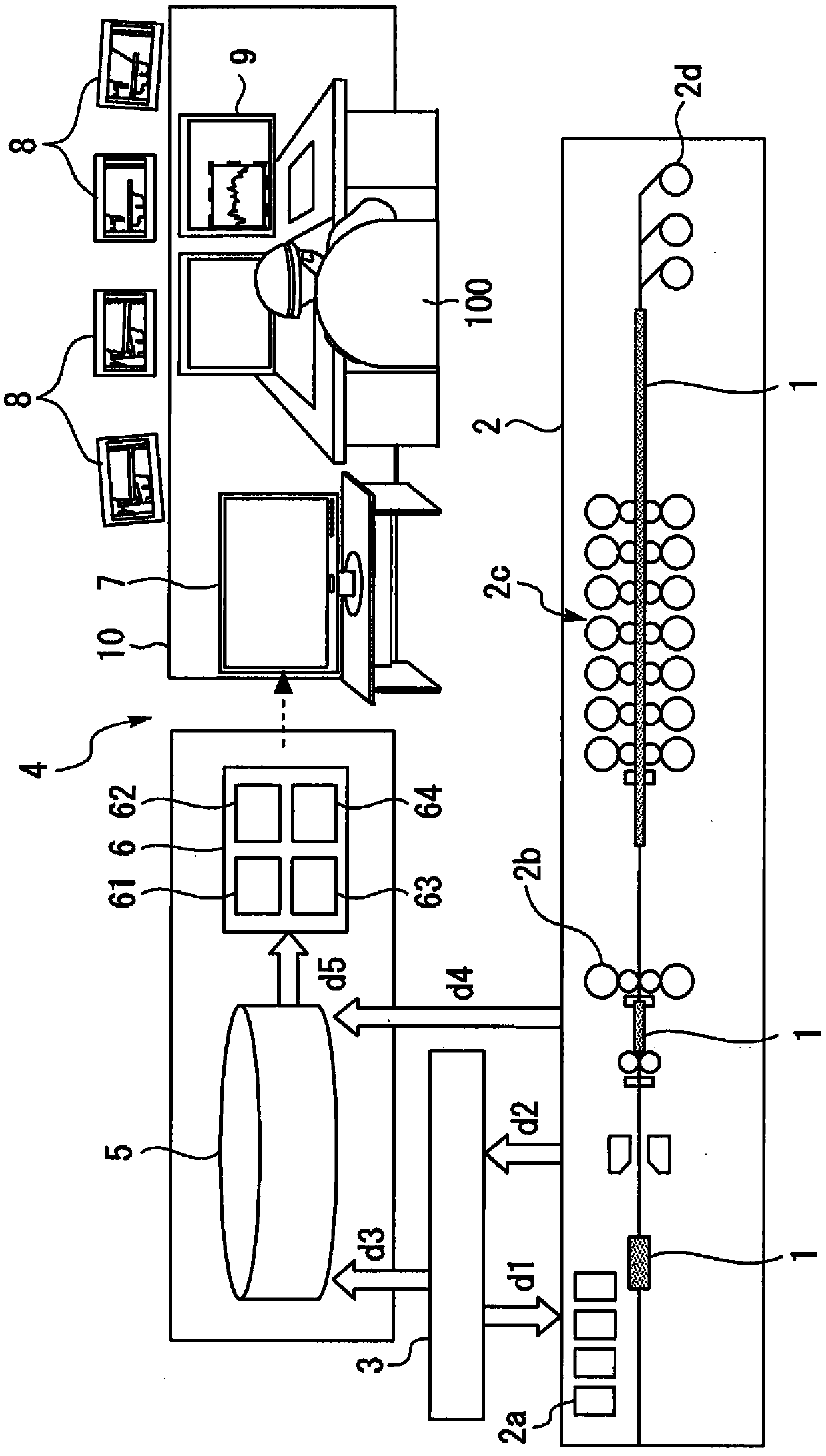
[0036] figure 1 It is a schematic diagram showing the data flow used in steel plants and systems to which the surveillance operation support system is applied.

[0037] In the rolling line 2, the high-temperature thick plate (to-be-rolled material 1) heated by the heating furnace 2a is conveyed by conveying rolls, and processed while stretching to a target plate thickness in the rough rolling mill 2b and finishing rolling mill 2c. The plate is widened and cooled, and finally coiled by the coiler 2d to produce a product (coil).

[0038] The control system 3 transmits command data d1 for operation to each equipment of the rolling line 2 . In addition, sensors are installed on each equipment of the rolling line 2, and the control system 3 collects measured actual data through them. Actual data are broadly divided into two types: actual data d2 used in the control system 3 and actual data d4 used for analysis or evaluation without being used by the c...


PUM


Abstract

A monitoring work support system for an iron and steel plant supports visual confirmation of a data waveform throughout the entire length of a material to be rolled and determines the monitoring workof an operator having an abnormality. The data storage unit stores actual data of full-length data constituted by measured values of predetermined data items at each point in the longitudinal direction of the material to be rolled. The exception graph pattern registration unit registers at least one piece of exception full-length data for the data item. The similarity determination unit determinesthat the waveform is similar when the square root ratio of the mean value of the square of the deviation between D1_dev[i] and D2_dev[i] is smaller than a threshold value. D1_dev [i] is the deviationbetween the value D1[i] of each point i (i=1,..., N) of the actual data and the average value avi1 of the actual data, and D2_dev[i] is the deviation between the value D2[i] of each point [i] of theabnormal full-length data and the average value avi2 of the abnormal full-length data. The message output unit outputs a pre-registered warning message when the similarity determination unit determines that the waveform is similar.

Description

technical field [0001] The present invention relates to a monitoring operation support system for iron and steel plants. Background technique [0002] Due to the advancement of science and technology so far, automation of equipment has been developed by making full use of control technology and system technology in many processes in steel plants. However, the complete automation of the entire factory has not yet been achieved. Currently, the work that requires improvised judgment, which is difficult for machines, is still performed manually. As a result, the operation of the entire factory can be carried out without stagnation. [0003] A worker monitors the automated equipment from an operation room (referred to as a control room) arranged at a position where the equipment can be observed. In the operation room, in order to grasp the working status of the equipment, there are monitors that reflect the equipment and the rolled material captured by multiple cameras, monitors...

Claims


Application Information

Patent Timeline
IPC IPC(8): G05B19/418
CPCG05B19/41875Y02P90/02Y02P90/30G06Q50/10G06Q50/04G06Q10/06395
Inventor 井波治树
Owner TOSHIBA MITSUBISHI-ELECTRIC IND SYST CORP
Why Eureka
Try Eureka