
High-performance crystalline silicon battery assembly and solar battery panel

A crystalline silicon cell, high-performance technology, applied in the field of solar photovoltaics, which can solve the problems of complex layout, long bus bars, and difficult handling.

Inactive Publication Date: 2019-12-31
SUZHOU TALESUN SOLAR TECH CO LTD
View PDF5 Cites 0 Cited by
  • Summary
  • Abstract
  • Description
  • Claims
  • Application Information

AI Technical Summary

Problems solved by technology

[0002] With the rapid development of high-efficiency batteries, the battery Is (short-circuit current) continues to increase. In order to reduce Rs (series resistance), slice welding has become a trend. The existing half-chip modules are popular, but the existing crystalline silicon battery module layout Complicated, the bus bar is too long, it is difficult to handle in actual operation

Method used


Image

  • High-performance crystalline silicon battery assembly and solar battery panel
  • High-performance crystalline silicon battery assembly and solar battery panel
  • High-performance crystalline silicon battery assembly and solar battery panel

Examples


Embodiment 1

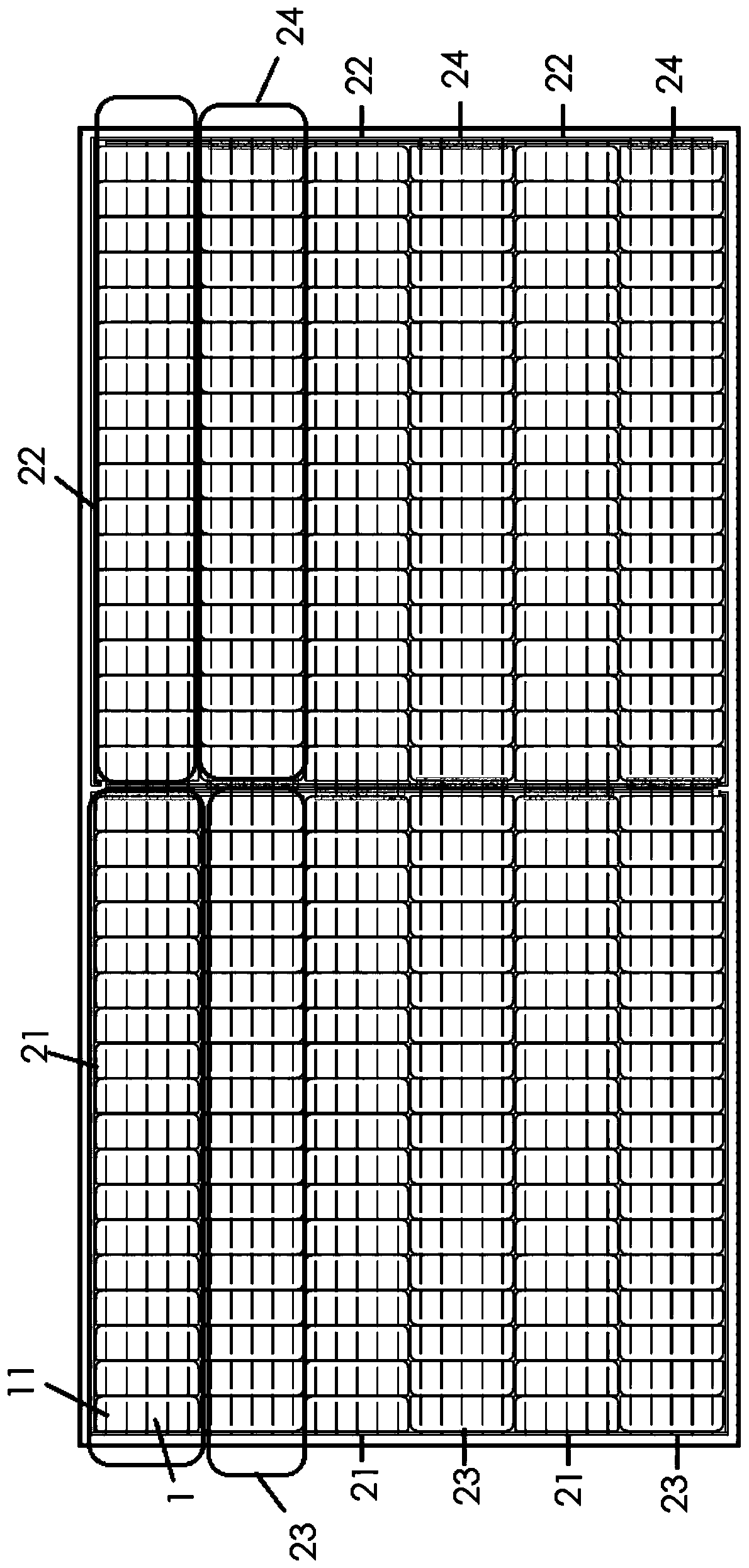
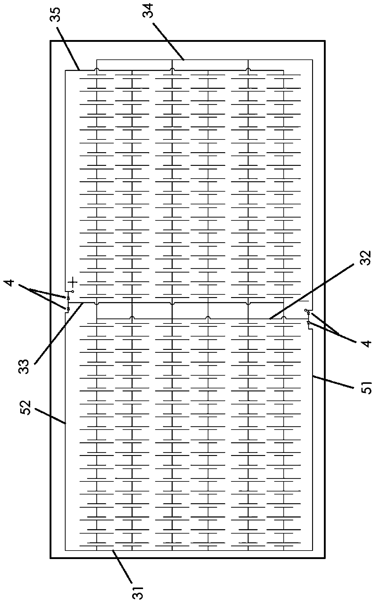
[0070] Embodiment one, such as Figure 1-3 As shown, the first longitudinal bus bar 31 is electrically connected to the fourth longitudinal bus bar 34 through the first transverse bus bar 51, and two diodes 4 are arranged in series on the first transverse bus bar 51;

[0071] The second longitudinal bus bar 32 is electrically connected to the conductive part between the two series diodes 4 arranged on the first transverse bus bar 51;

[0072] The first longitudinal bus bar 31 is electrically connected to the fifth longitudinal bus bar 35 through the second transverse bus bar 52, and two diodes 4 are also arranged in series on the second transverse bus bar 52;

[0073] The third longitudinal bus bar 33 is electrically connected to the conductive part between the two series diodes 4 arranged on the second transverse bus bar 52;

[0074] The lengths of the first transverse bus bar 51 and the second transverse bus bar 52 are parallel to the long sides of the crystalline silicon b...

Embodiment 2

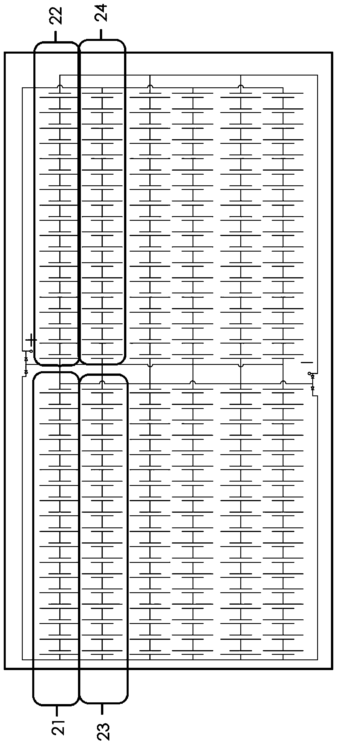
[0076] Embodiment two, such as Figure 4-6 As shown, the first longitudinal bus bar 31 is electrically connected to the fifth longitudinal bus bar 35 through the third transverse bus bar 53 and the fourth transverse bus bar 54 in turn, and two diodes 4 are arranged in series on the fourth transverse bus bar 54 ;

[0077] The third longitudinal bus bar 33 is electrically connected to the conductive part between the two series diodes 4 arranged on the fourth transverse bus bar 54;

[0078] The first longitudinal bus bar 31 is electrically connected to the fourth longitudinal bus bar 34 through the third transverse bus bar 53 and the fifth transverse bus bar 55 in turn, and two diodes 4 are also arranged in series on the fifth transverse bus bar 55;

[0079] The second longitudinal bus bar 32 is electrically connected to the conductive part between the two series diodes 4 arranged on the fifth transverse bus bar 55;

[0080] The lengths of the third transverse bus bar 53, the f...


PUM


Abstract

The invention discloses a high-performance crystalline silicon battery assembly and a solar battery panel. The battery assembly includes a plurality of crystalline silicon battery strings, bus bars and two diodes, wherein the crystalline silicon battery strings are formed by connecting a plurality of small crystalline silicon battery pieces, the small crystalline silicon battery pieces are formedby cutting photovoltaic battery pieces, and at least three small crystalline silicon battery pieces are cut from one photovoltaic battery piece, a plurality of crystalline silicon battery strings areconnected in one or more connection modes of series connection, parallel connection and series-parallel connection to form the crystalline silicon battery assembly, four diodes are arranged at leading-out ends of the crystalline silicon battery assembly, and the leading-out ends of the crystalline silicon battery assembly are arranged at middle parts of two opposite sides or one side of the long side of the crystalline silicon battery assembly. The battery assembly is advantaged in that the output power of the assembly can be improved, overall mechanical load resistance of the assembly is improved, and hot spot resistance is improved.

Description

technical field [0001] The invention belongs to the field of solar photovoltaics, and in particular relates to a high-performance crystalline silicon battery assembly and a solar photovoltaic battery board. Background technique [0002] With the rapid development of high-efficiency batteries, the battery Is (short-circuit current) continues to increase. In order to reduce Rs (series resistance), slice welding has become a trend. The existing half-chip modules are popular, but the existing crystalline silicon battery module layout Complicated, the bus bar is too long, and it is difficult to handle in actual operation. Contents of the invention [0003] In order to solve the above technical problems, the present invention proposes a high-performance crystalline silicon cell assembly and a solar photovoltaic cell panel. [0004] In order to achieve the above object, technical scheme of the present invention is as follows: [0005] A high-performance crystalline silicon batt...

Claims


Application Information

Patent Timeline
Patent Type & Authority Applications(China)
IPC IPC(8): H01L31/05H01L31/044
CPCH01L31/044H01L31/0508Y02E10/50
Inventor 陆文华倪志春蔡霞陈成锦柯坡曹海波余嫦吴镇
Owner SUZHOU TALESUN SOLAR TECH CO LTD
Learn More