
De-metalized conformal dielectric resonator antenna

A dielectric resonator and demetallization technology, applied to antennas, antennas suitable for movable objects, antenna components, etc., can solve the problem of free control of frequency and bandwidth, insufficient freedom of antenna design, and insufficient design methods Mature and other issues, to achieve wide beam width, easy to understand, reduce the effect of design and application difficulty

Pending Publication Date: 2019-12-31
CHENGDU BEIDOU ANTENNA ENG TECH +1
View PDF0 Cites 1 Cited by
  • Summary
  • Abstract
  • Description
  • Claims
  • Application Information

AI Technical Summary

Problems solved by technology

[0004] Due to the advantages of high radiation efficiency, low self-loss, multiple radiation modes, easy integration, and diversity of resonator shapes and feeding methods, dielectric resonators have gradually received extensive attention and research in many fields, but there are few in the market. Some people apply many advantages of dielectric resonator antennas to emerging conformal devices, and their design methods are also very immature. The lack of tuning theory directly leads to insufficient freedom in the design of such antennas, and it is difficult to achieve free control of frequency and bandwidth.
Common dielectric resonator antennas are often tuned using metal structures based on the mirror image principle and perturbation method or coupling theory. This method re-introduces metal structures into the dielectric antenna, which has certain ohmic losses and is not suitable for high frequencies.

Method used


Image

  • De-metalized conformal dielectric resonator antenna
  • De-metalized conformal dielectric resonator antenna
  • De-metalized conformal dielectric resonator antenna

Examples


Embodiment 1

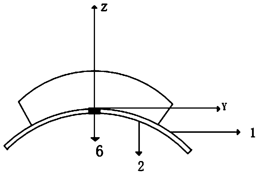
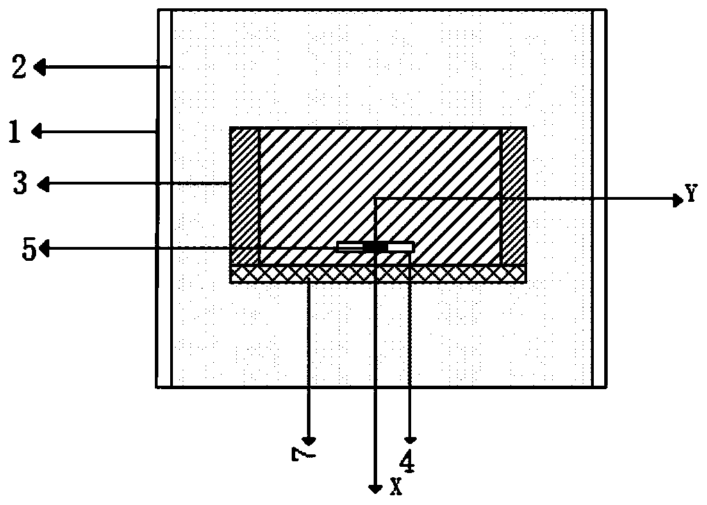
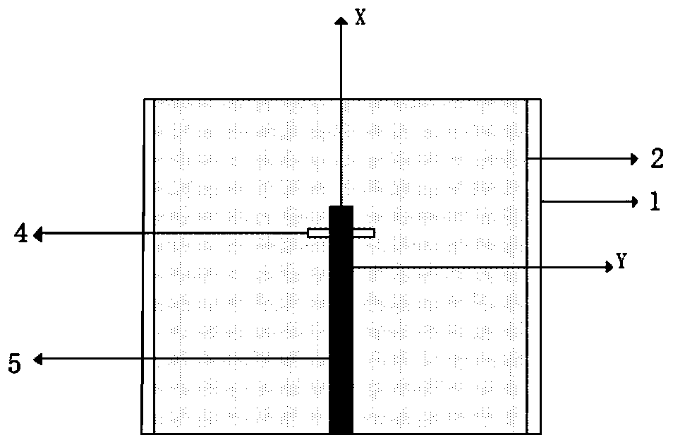
[0036] Such as Figure 1 to 3 As shown, a demetallized conformal dielectric resonator antenna includes: a floor 1, a dielectric substrate 2, a dielectric resonator 3, a feed slot 4, a feed line 5, a feed port 6 and a dielectric loading structure 7;

[0037] The floor 1 and the dielectric resonator 3 are arc-shaped and conformal, and the dielectric resonator 3 is fixed in the middle of the upper surface of the floor 1;

[0038] The upper surface of the dielectric substrate 2 is attached to the floor 1, and the lower surface is attached to the feeder 5; a feed slot 4 is etched in the center of the floor 1; at the same time, there is a feed port 6 at the connection of the floor 1 and the dielectric substrate 2;

[0039] The front surface of the dielectric resonator 3 (relative to the standard Yoz coordinate plane) tightly fits the back surface of the dielectric loading structure 7 (relative to the standard Yoz coordinate plane), while the dielectric resonator 3 and the dielectric loadin...

Embodiment 2

[0050] Embodiment 2. This embodiment only illustrates the difference from Embodiment 1;

[0051] Such as Image 6 , 7 As shown, the dielectric resonator 3 is made of a composite ceramic dielectric copper clad material with a dielectric constant of 10, and the dielectric loading structure 7 is made of a ceramic loaded composite board material with a dielectric constant of 4. The width of the dielectric resonator 3 is 30mm , The thickness is 10mm, the bottom arc length is 52.3mm, and the top arc length is 62.8mm. The width of the media loading structure 7 is 10mm, the thickness is 10mm, the bottom arc length is 52.3mm, the top arc length is 62.8mm, and the arc is 60 degrees; the width of the floor 1 is 70mm, and the arc length is 104.7mm. The substrate 2 is made of a composite ceramic dielectric copper-clad material with a dielectric constant of 2.2. The width of the dielectric substrate 2 is 70mm, the height is 0.6mm, and the arc length of the arc side is 104.7mm;

[0052] The leng...


PUM


Abstract

The invention also discloses a de-metalized conformal dielectric resonator antenna, which includes a floor, a dielectric substrate, a dielectric resonator, a feed slit, a feeder line, a feed port, anda dielectric loading structure. The floor and the dielectric resonator exhibit an arc-shaped conformal feature. The dielectric resonator is fixed to the upper surface of the floor. The upper surfaceof the dielectric substrate is attached to the floor, and the lower surface of the dielectric substrate is attached to the feeder line. The feed slit is etched in the center of the floor. The feed port is located at the joint between the floor and the dielectric substrate. The front surface of the dielectric resonator is attached to the rear surface of the dielectric loading structure, and the dielectric resonator and the dielectric loading structure are fixed to the upper surface of the floor. The antenna achieves feeding by the feeder line. Then, the electromagnetic wave energy is coupled and transferred to the dielectric resonator on the upper surface through the feed slit on the floor. The de-metalized conformal dielectric resonator antenna has a good tuning structure and improved design degree of freedom, realizes flexible control of size and bandwidth, realizes de-metallization, reduces design and application difficulty, and has a wider beam width and higher gain.

Description

Technical field [0001] The present invention relates to the technical field of conformal antennas, in particular to a demetallized conformal dielectric resonator antenna. Background technique [0002] With the rapid development of wireless communication technology, wireless communication devices have begun to develop in the direction of portability, and various wearable electronic devices have emerged as the times require, which also makes the antenna design develop in a conformal direction. [0003] Conformal antenna refers to an antenna that is consistent with the shape of the object structure and does not bring additional burden to the conformal device. The antenna array is "conformal" with the shape of the carrier, which enhances the adaptability. The array antenna has great advantages. In modern wireless communication systems, conformal array antennas have become one of the best in the field of antennas because they can conform to the surface of high-speed carrier platforms s...

Claims


Application Information

Patent Timeline
Patent Type & Authority Applications(China)
IPC IPC(8): H01Q1/38H01Q1/48H01Q1/50H01Q1/27H01Q5/10
CPCH01Q1/38H01Q1/48H01Q1/50H01Q1/273H01Q5/10
Inventor 潘锦刘岩马伯远杨德强刘贤峰王恩浩
Owner CHENGDU BEIDOU ANTENNA ENG TECH
Learn More