Offshore wind power plant topological structure and control method thereof
A topology and fan technology, applied in parallel operation of DC power supply, harmonic reduction device, AC network to reduce harmonic/ripple, etc., can solve the problems of large converter station, high operating loss, narrow application range, etc. , to achieve high reliability, strong practicability, and improve the effect of practicability and reliability
- Summary
- Abstract
- Description
- Claims
- Application Information
AI Technical Summary
Problems solved by technology
Method used
Image
Examples
Embodiment 1
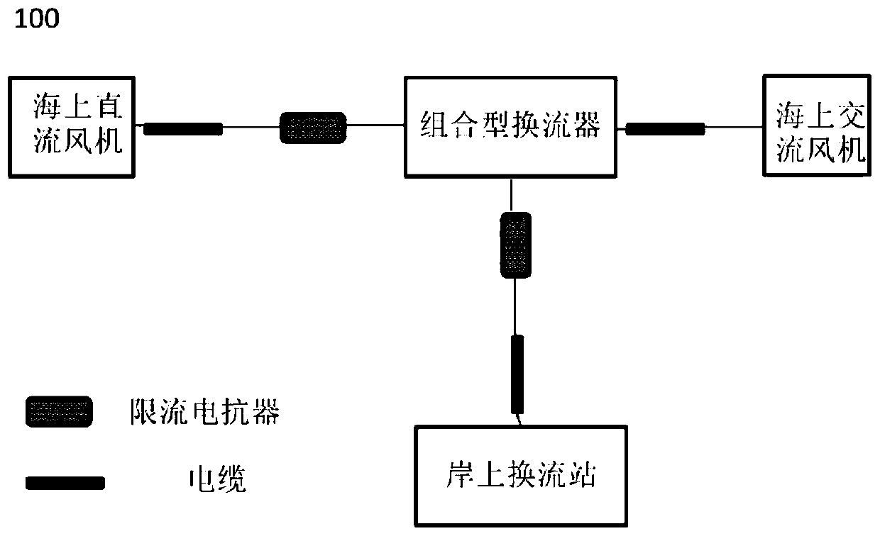
[0050] A topological structure 100 of an offshore wind farm, such as figure 1 As shown, including: multiple offshore DC wind turbines, multiple offshore AC wind turbines, and combined converters;
[0051] The first DC port of the combined converter is connected to the first DC cable through the first current-limiting reactor, and then connected to each of the offshore DC wind turbines through the first DC cable; the AC port is connected through the AC cable Connected to each of the offshore AC wind farms; the second DC port is connected to the second DC cable through the second current-limiting reactor, and then externally connected to the onshore converter station through the second DC cable, for simultaneously collecting offshore DC The energy sent by the fan and the offshore AC fan is sent to the onshore converter station in the form of high-voltage direct current.
[0052] Such as figure 2 As shown in Fig. 1, the existing typical topology structure of offshore wind farm...
example 1
[0068] Example 1, the second converter unit 312 is composed of a twelve-pulse uncontrolled rectifier 312-1, a three-phase three-winding converter transformer 312-2, and a bypass switch 312-3. One winding of the three-phase three-winding converter transformer 312 - 2 is connected to the common AC bus 314 inside the combined converter 31 , and the common AC bus 314 is connected to the first AC port of the energy collection system 3 . The other two windings of the three-phase three-winding converter transformer 312-2 are respectively connected to the AC ports of the twelve-pulse uncontrolled rectifier 312-1. The bypass switch 312-3 is connected across the positive and negative busbars of the twelve-pulse uncontrolled rectifier 312-1, and is used to close when the second converter unit 312 fails, and bypass the second converter unit 312. to maintain the continuous operation of the non-faulty area of the combined converter 31.
[0069] The third converter unit 313 is composed of...
example 2
[0070] Example 2, such as Figure 7 As shown, the second converter unit 312 or the third converter unit 313 consists of a six-pulse uncontrolled rectifier 312-4, a three-phase double-winding converter transformer 312-5, and a bypass switch 312-6. One winding constituting the three-phase double-winding converter transformer 312 - 5 is connected to the common AC bus 314 inside the combined converter 31 , that is, the first AC port. The other winding of the three-phase two-winding converter transformer 312-5 is connected to the AC port of the six-pulse uncontrolled rectifier 312-4. The bypass switch 312-6 is connected across the positive and negative busbars of the six-pulse uncontrolled rectifier 312-4, and is used to close when the six-pulse uncontrolled rectifier 312-4 fails, so that the six-pulse uncontrolled rectifier 312-4 performs a bypass to maintain the continuous operation of the non-faulty area of the combined converter 31.
PUM
 Abstract
Description
Claims
Application Information
 - R&D
- Intellectual Property
- Life Sciences
- Materials
- Tech Scout
- Unparalleled Data Quality
- Higher Quality Content
- 60% Fewer Hallucinations
Browse by: Latest US Patents, China's latest patents, Technical Efficacy Thesaurus, Application Domain, Technology Topic, Popular Technical Reports.
© 2025 PatSnap. All rights reserved.Legal|Privacy policy|Modern Slavery Act Transparency Statement|Sitemap|About US| Contact US: help@patsnap.com


