Wireless charging electronic equipment, method and system

A technology of electronic equipment and wireless charging, which is applied to battery circuit devices, current collectors, electric vehicles, etc., can solve the problems of low charging efficiency, achieve the effects of improving work efficiency, improving wireless charging experience, and enhancing cooperation

Active Publication Date: 2019-12-31
HUAWEI DIGITAL POWER TECH CO LTD
View PDF7 Cites 10 Cited by
  • Summary
  • Abstract
  • Description
  • Claims
  • Application Information

AI Technical Summary

Problems solved by technology

However, there is a problem of low charging efficiency in the wireless charging system. How to improve the efficiency of wireless charging, especially the efficiency inside the terminal device, has become a current research hotspot.

Method used


Image

  • Wireless charging electronic equipment, method and system
  • Wireless charging electronic equipment, method and system
  • Wireless charging electronic equipment, method and system

Examples


Embodiment 1

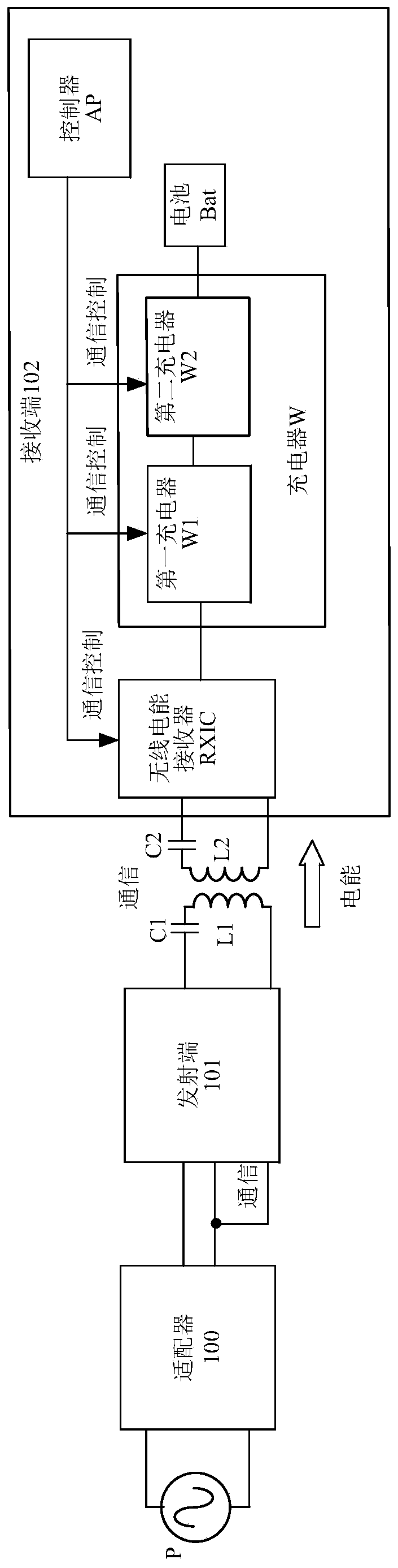
[0159] see figure 1 , which is a schematic diagram of a wireless charging system architecture provided by an embodiment of the present application, from which the architecture of the receiving end can be seen.

[0160] Such as figure 1 As shown, the wireless charging system includes: a power supply P, an adapter 100 , a transmitter 101 and a receiver 102 . The receiving end 102 is a wireless charging electronic device provided in the embodiment of this application. As an example, the electronic device 102 may be a mobile phone, a tablet computer, a notebook computer, a Bluetooth headset, a smart watch, an electric toothbrush, and the like that can be charged through wireless charging.

[0161] The transmitting end 101 and the receiving end 102 respectively have coils, wherein the coil of the transmitting end 101 is called the transmitting coil L1, and the coil of the receiving end 102 is called the receiving coil L2. The transmitting coil L1 and the first resonant capacitor...

Embodiment 2

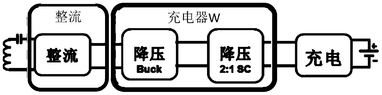
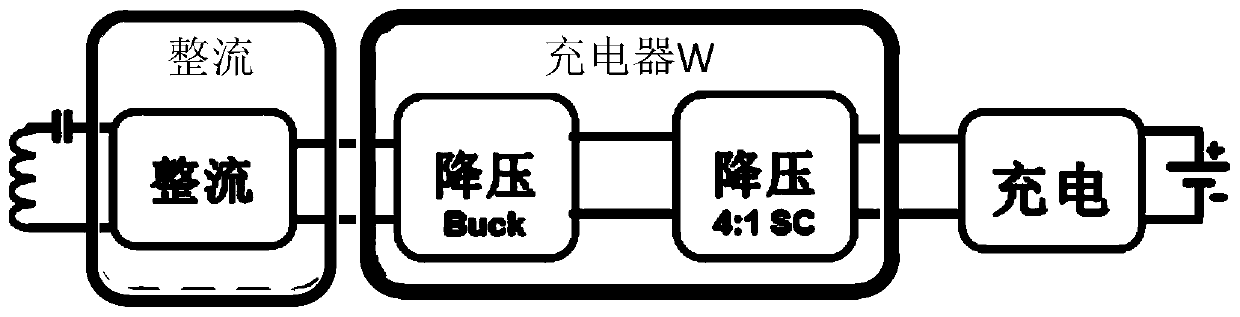
[0173] see image 3 , which is a schematic diagram of a wireless charging system architecture provided in this embodiment.

[0174] Such as image 3 As shown, the charger W at the receiving end 102 in this system includes two parallel chargers, namely the first charger W1 and the second charger W2, wherein the first charger W1 includes at least one closed-loop DC-DC converter , the second charger W2 includes at least one open-loop DC-DC converter. When the first charger W1 works in the step-down mode, the second charger W2 is prohibited from working; when the second charger W2 works in the step-down mode, the first charger W1 is prohibited from working.

[0175] When the controller AP controls the open-loop DC-DC converter to work in the fast charging stage, it controls the closed-loop DC-DC converter to work in the through state or the disconnected state. The disconnected state means that the operation of the closed-loop DC-DC converter is disabled. for image 3 In the s...

Embodiment 3

[0212] see Figure 6 , which is a schematic structural diagram of a wireless charging system provided in this embodiment.

[0213] Such as Figure 6 As shown, the power supply P, the adapter 100 , the transmitting end 101 and the receiving end 102 . compared to image 3 , Figure 6 The receiving end 102 shown further includes a step-down DC-DC circuit 103 between the wireless power receiver RXIC and the input end of the charger W.

[0214] The charger W specifically includes a first charger W1 and a second charger W2, wherein the first charger W1 includes at least one closed-loop DC-DC converter, and the second charger W2 includes at least one open-loop DC-DC converter. In the receiving end 102 , the receiving coil L2 couples the AC power generated by the transmitting coil L1 of the transmitting end 101 to realize energy transmission from the transmitting end 101 to the receiving end 102 . The wireless power receiver RXIC is connected to the second resonant network (inclu...


PUM


Abstract

The invention discloses wireless charging electronic equipment, method and system. A charger at a receiving end of the system comprises an open-loop DC-DC converter. When transmitting end power is greater than a first preset threshold of a transmitting end and charging demand power is greater than the first preset threshold of a receiving end, the open-loop DC-DC converter is controlled to work in a fast charging stage, specifically, the open-loop DC-DC converter is controlled to work in a constant-current voltage reduction stage to charge a battery with a constant current, or a switch DC-DCconverter is controlled to work in a constant-voltage voltage reduction stage to charge the battery with a constant voltage. Compared with the prior art, by using the technical scheme of the invention, a power capability of the transmitting end is effectively combined to carry out charging control, wireless charging efficiency of the receiving end is improved, working efficiency of the transmitting end is increased, and the power capability of the transmitting end is fully used so that charging stability is also improved.

Description

technical field [0001] The present application relates to the technical field of terminal equipment, and in particular to an electronic equipment, method and system for wireless charging. Background technique [0002] Portable electronic devices have been widely used in recent years. The traditional way of charging electronic equipment often requires frequent plugging and unplugging of the power cord, but the device is prone to wear and tear during the plugging and charging process, which has poor safety and also affects the appearance of the electronic equipment. [0003] Wireless charging is a new type of energy transmission. Compared with traditional charging methods, wireless charging can solve the above problems well. Nowadays, many electronic devices can support wireless charging, such as mobile phones, smart watches, Bluetooth headsets, electric toothbrushes, etc. However, there is a problem of low charging efficiency in the wireless charging system. How to improve...

Claims


Application Information

Patent Timeline
Patent Type & Authority Applications(China)
IPC IPC(8): H02J7/04H02J7/02
CPCH02J50/12H02J7/00712H02J7/00714H02J7/007182H02J50/80H02J7/06H02M1/007H02M3/01H02M3/335Y02B40/00H02J7/00032H02J2207/20H02J7/04
Inventor 吴宝善杨云鹏张成良蔡兵吴东昊
Owner HUAWEI DIGITAL POWER TECH CO LTD
Why Eureka
Try Eureka