
Permanent magnet synchronous motor rotor structure applied to novel electric vehicle

A permanent magnet synchronous motor, electric vehicle technology, applied in electric vehicles, synchronous motors with static armatures and rotating magnets, magnetic circuit shape/style/structure, etc. content, radial force harmonic motor vibration and noise, etc., to achieve the effect of improving radial force wave, reducing harmonic content, and reducing vibration and noise

Inactive Publication Date: 2019-12-31
HANGZHOU DIANZI UNIV
View PDF7 Cites 0 Cited by
  • Summary
  • Abstract
  • Description
  • Claims
  • Application Information

AI Technical Summary

Problems solved by technology

In the case of a uniform air gap, the air gap magnetic density of the rectangular permanent magnet synchronous motor presents a trapezoidal distribution. This magnetic density distribution has a large harmonic content, which will generate serious radial force harmonics and cause motor vibration and vibration. Noise, affecting the NVH characteristics of the vehicle

Method used


Image

  • Permanent magnet synchronous motor rotor structure applied to novel electric vehicle
  • Permanent magnet synchronous motor rotor structure applied to novel electric vehicle
  • Permanent magnet synchronous motor rotor structure applied to novel electric vehicle

Examples


Embodiment Construction

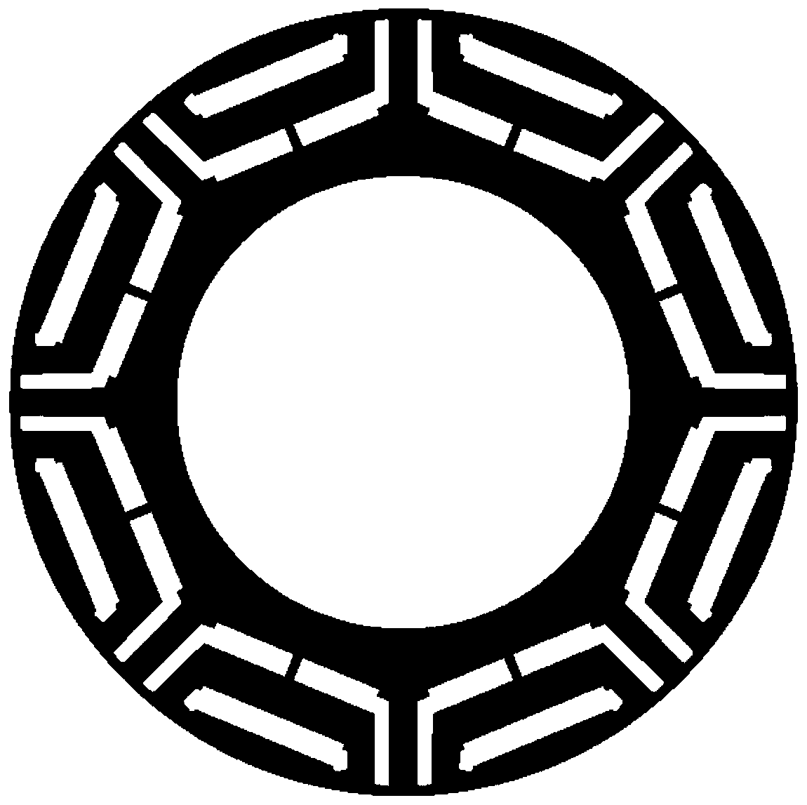
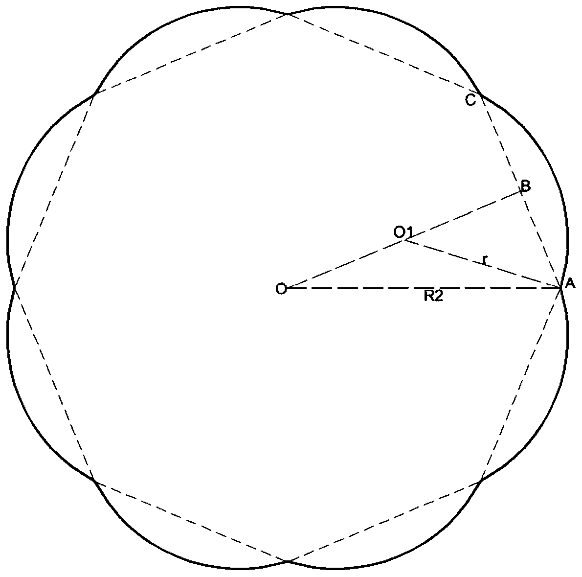
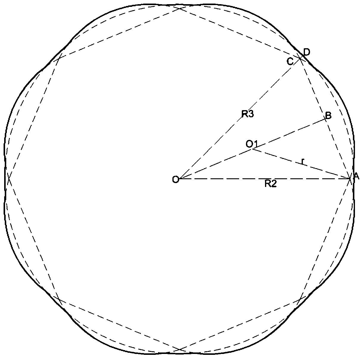
[0025] The present invention is according to 4 pairs of poles 48 slot permanent magnet synchronous motor rotor stampings (such as figure 1 ) to carry out innovative inventions, take the origin O of the original permanent magnet synchronous motor rotor punching sheet as the center to establish a regular octagon with a radius of R2, R2 figure 2 The graph shown. Make a circle with O as the center and R3 as the radius, and intersect the arc drawn above as image 3 , where R2 Figure 4 . Using the original permanent magnet synchronous motor stator structure and winding mode, R2 and R3 are used as parameters, and the air gap flux density distortion rate is used as a reference target to conduct parametric analysis with Maxwell, in which R2 and R3 are controlled to control the minimum and maximum air gaps respectively ,like Figure 5 shown. According to the inner diameter of the stator core in the original permanent magnet synchronous motor structure is 57mm, the optimal R2 here is ...


PUM


Abstract

The invention discloses a permanent magnet synchronous motor rotor structure applied to a novel electric vehicle. According to the invention, on a permanent magnet synchronous motor with 4 pairs of poles and 48 slots and uniform air gap spacing, a regular polygon is established based on the circle center of the rotor punch of the permanent magnet synchronous motor; R1 is greater than R2, where R1is the radius of the rotor punch of the permanent magnet synchronous motor, and R2 is the radius of the regular polygon; the center point of the rotor of the permanent magnet synchronous motor is theorigin, and the center point of the vertical line from the origin to the edge of the octagon is a dot; the arc with the radius from the dot to the nearest octagon vertex is the outer contour of the rotor punch of a new permanent magnet synchronous motor; the origin is used as the center and R3 is used as the radius to make a circle and superimpose the circle and the outer contour of the rotor punch of the new permanent magnet synchronous motor to acquire the rotor structure. According to the invention, non-uniform air gaps are used, so that the air gap magnetic density is in sinusoidal distribution; the harmonic content is reduced; the radial force wave is well improved; and the vibration and noise of the permanent magnet synchronous motor are reduced.

Description

Technical field [0001] The invention belongs to the field of permanent magnet synchronous motors for electric vehicles; specifically, it relates to a new permanent magnet synchronous motor rotor structure that optimizes the radial force waveform of the permanent magnet synchronous motor. Background technology [0002] In recent years, with the gradual implementation of electric vehicle industry policies and people's increasing concern for environmental and energy issues, electric vehicles have gradually been chosen by more and more consumers. Permanent magnet synchronous motors have the advantages of high efficiency, high speed and high power density, and have become the first choice for permanent magnet synchronous motors for vehicles. Currently, most of the domestic market uses permanent magnet synchronous motors as power sources. [0003] Although permanent magnet synchronous motors have significant advantages, since electric vehicles do not have roaring engine noise, the...

Claims


Application Information

Patent Timeline
Patent Type & Authority Applications(China)
IPC IPC(8): H02K1/27H02K21/14
CPCH02K1/27H02K21/14H02K2201/03H02K2213/03Y02T10/64
Inventor 刘栋良屈峰崔丽丽李阿强杨响攀
Owner HANGZHOU DIANZI UNIV
Learn More