Falling film type devolatilizer and falling film element thereof

A devolatilizer and falling film technology, applied in the field of chemical production equipment, can solve the problems of limited flow range of production materials, difference in residence time, reduction in residence time, etc., to meet the requirements of large capacity, high quality, uniform and controllable residence time, Controllable effect of film formation

Pending Publication Date: 2020-01-03
ZHEJIANG SCI-TECH UNIV +1
View PDF2 Cites 2 Cited by
  • Summary
  • Abstract
  • Description
  • Claims
  • Application Information

AI Technical Summary

Problems solved by technology

[0005] The disclosed vertical devolatilization reactor (a falling film polycondensation reactor outside the tube tube, CN102746499 B; a multi-layer falling tube type falling film devolatilization reactor, CN105903424 B), because it does not have an agitator, Therefore, the energy consumption is reduced, and the film formation and surface renewal can also meet certain production quality requirements, but the range of production material flow that can be adjusted is limited. When the material handling capacity is increased, the residence time is significantly reduced, and the product quality is reduced; and With the multi-layer shed structure, when the material leaves the shed during the falling film process, it is easy to cause direct fall and cannot return to the outer wall of the hollow tube, forming a so-called "short circuit", which makes the devolatilization effect worse and the viscosity of the material is uneven. , the multi-layer structure will also gradually increase the viscosity of the material, which will easily cause a significant difference in residence time when the lower tray flows radially, thereby affecting the devolatilization effect

Method used


Image

  • Falling film type devolatilizer and falling film element thereof
  • Falling film type devolatilizer and falling film element thereof
  • Falling film type devolatilizer and falling film element thereof

Examples


Embodiment 1

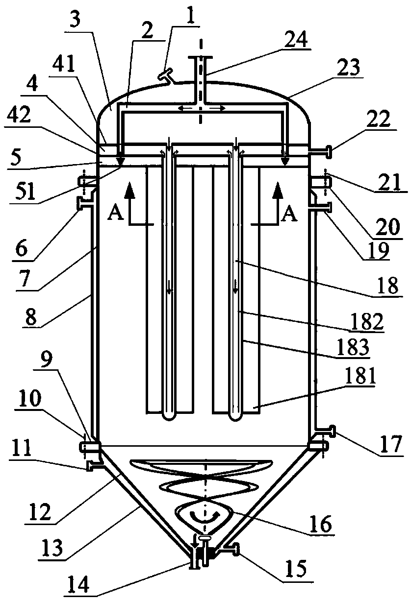
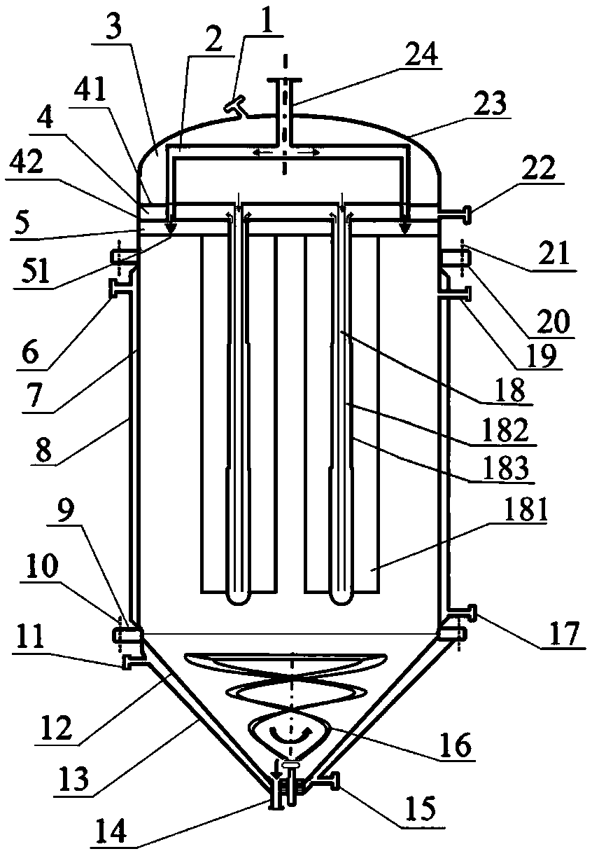
[0043] Embodiment 1, with reference to attached figure 1 , image 3 and Figure 10 ;

[0044] A falling film devolatilizer provided in this embodiment, such as figure 1 As shown, it includes a vertical shell 7, a cover head 23 connected to the upper end of the vertical shell 7, a bottom shell 12 at the lower end, a material inlet 24, a vacuum pumping port 21, and a material outlet 14. The devolatilizer is provided with a material box body 5 and a plurality of falling film elements 18, there are a plurality of falling film flow channels 18a on the falling film element 18, the material inlet 24 communicates with the material box body 5, and the bottom plate of the material box body 5 is a cloth film plate 51, and a cloth film plate 51 A film cloth structure is provided, and each falling film channel 18a is assigned a film cloth structure.

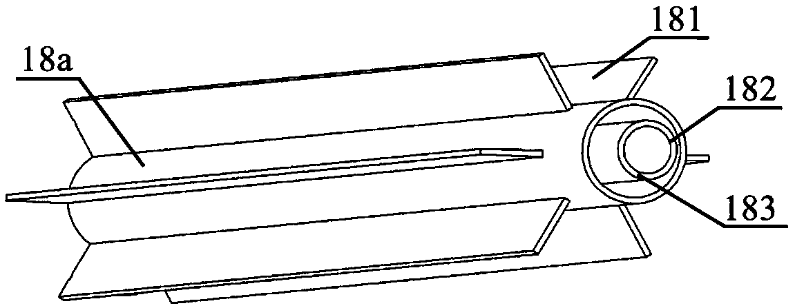
[0045] A plurality of axial limiting walls 181 are distributed on the outer periphery of the falling film element 18, and the falling fi...

Embodiment example 2

[0060] With intrinsic viscosity being 0.65dL / g the PET melt that molecular weight distribution index is 1.65 is as raw material, carry out devolatilization reaction to produce high molecular weight PET, the flow rate of each falling film element is 20kg / h, other parts are the same as embodiment 1, can The intrinsic viscosity of the obtained product was 1.01dL / g, and the molecular weight distribution index was 1.53.

Embodiment example 3

[0062] like Figure 4 As shown, the falling film element 18 with an axial stop wall is a straight pipe with a constant diameter, and there are crosspieces 184 equally spaced between the adjacent axial stop walls 181 on the falling film element 18, and other The part is the same as in Example 1; using the optimal structure scheme, using PET melt with an intrinsic viscosity of 0.65dL / g and a molecular weight distribution index of 1.65 as raw material, the devolatilization reaction is carried out to produce high molecular weight PET, and the flow rate of each falling film element is 20kg / h, the intrinsic viscosity of the obtained product is 1.02dL / g, and the molecular weight distribution index is 1.51.


PUM

PropertyMeasurementUnit
diameteraaaaaaaaaa
lengthaaaaaaaaaa
diameteraaaaaaaaaa

Abstract

The invention relates to a falling film type devolatilizer and a falling film element thereof. The falling film type devolatilizer comprises a vertical shell, a seal head connected with the upper endof the vertical shell, and a bottom shell connected with the lower end of the vertical shell; a material box body and at least one falling film element are arranged in the devolatilizer; the falling film element is provided with a plurality of falling film flow channels; a bottom plate of the material box body is a film distribution plate; and film distribution structures are distributed on the film distribution plate for all the falling film flow channels. The devolatilizer has the advantages of large film forming area, controllable film forming form, wide flow regulation range and the like,and is suitable for devolatilization processes such as high-viscosity polymer production, spinning solution deaeration, solution concentration and the like.

Description

technical field [0001] The invention relates to a falling-film devolatilization equipment used in the fields of polymer production, spinning liquid degassing, solution concentration, vacuum evaporation, etc., in particular to a production device for polymer polycondensation reaction, belonging to the field of chemical production equipment. Background technique [0002] In chemical operations such as polycondensation, degassing of spinning dope, vacuum evaporation, and desorption, the mass transfer efficiency of gradually removing small molecular compounds is the key factor to control the devolatilization process. Since this type of process usually occurs in a high-viscosity system, the diffusion of small molecular compounds in the system is very difficult, and the devolatilization effect will be limited by the internal structure of the equipment for material flow and the mixing characteristics of material flow. It is necessary to develop a devolatilizer with compact structur...

Claims


Application Information

Patent Timeline
Patent Type & Authority Applications(China)
IPC IPC(8): B01J19/20B01J19/00
CPCB01J19/0053B01J19/1887B01J19/1893B01J19/20B01J2219/185
Inventor 陈文兴马建平陈世昌张先明王勇军
Owner ZHEJIANG SCI-TECH UNIV
Why Eureka
Try Eureka