Conveyor convenient to disassembly and move

A technology for conveyors and auxiliary conveyor belts, which is applied in the field of conveyors that are easy to disassemble and move, and can solve the problems of narrow width, large occupied space, and inconvenient movement, so as to reduce power consumption, reduce occupied space, and save transportation cost effect

Active Publication Date: 2020-01-03
XINXIANG VOCATIONAL & TECHN COLLEGE
View PDF4 Cites 0 Cited by
  • Summary
  • Abstract
  • Description
  • Claims
  • Application Information

AI Technical Summary

Problems solved by technology

[0002] Conveyor transportation is the main way of material transportation at present, and is widely used in various industries such as electronics, electrical appliances, machinery, tobacco, printing, food, etc. According to different needs, conveyors can be divided into fixed and movable. Mobile is generally used in industrial assembly line production, while mobile is flexibly used in temporary material transportation. In order to solve the problems of large space occupation and inconvenient movement of mobile conveyors in daily use, the transportation of mobile conveyors The width of the belt usually needs to be limited to a certain extent. In addition, moving wheels are installed on the mounting frame of the conveyor. Although the problem of wheel movement is solved, the width of the conveyor belt is narrowed, which limits the transmission efficiency of the wheels. In addition, in order to adjust the transmission efficiency of the conveyor belt , the ribs on both sides of the conveyor belt can be adjusted, but the ribs are optional, and only the width of the ribs on both sides can be limited, while the width of the conveyor belt has not changed, and the space occupied by the entire conveyor belt has not changed. will be limited by space

Method used


Image

  • Conveyor convenient to disassembly and move
  • Conveyor convenient to disassembly and move
  • Conveyor convenient to disassembly and move

Examples


Embodiment Construction

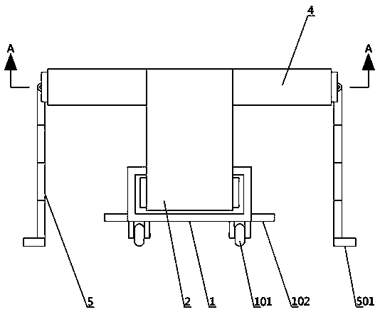
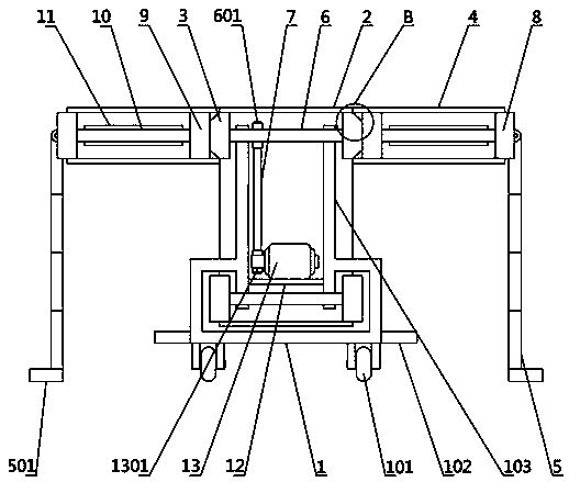
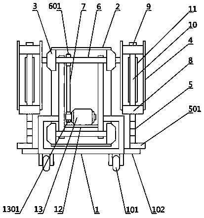
[0026] see Figure 1-8 , the present invention provides a technical solution: a conveyor that is easy to disassemble and move, including a base 1, a main conveyor belt 2, two auxiliary conveyor belts 4 and legs 5, the main body of the base 1 is open at the front and rear ends, and the upper A box structure with an opening in the middle of the side, the lower side of the base 1 is provided with a moving wheel 101, the left and right sides of the base 1 are provided near the lower end with a supporting plate 102 for supporting the load-bearing plate 501 at the lower end of the leg 5, and the upper middle opening of the base 1 is provided. There are two first support plates 103 parallel to each other, the four ends of the first support plate 103 are respectively connected to the four horizontally placed first rotating shafts 6, and both ends of the first rotating shaft 6 pass through the first supporting plate 103 at the corresponding position, And both ends of the first rotating...


PUM


Abstract

The invention discloses a conveyor convenient to disassembly. The conveyor comprises a base, a main conveyor belt, two auxiliary conveyor belts and landing legs; a conveyor motor of the conveyor and afirst rotary disc are in transmission connection though a conveyor belt, a first rotating shaft and the first rotary disc, and the first rotary disc drives the main conveyor belt to rotate; in addition, the first rotary disc and a third rotary disc are cooperatively connected, the third rotary disc is used for driving the auxiliary conveyor belts to rotate, a second rotating shaft connected to the third rotary disc is arranged on a second support plate, and a slide cavity of the second support plate is internally provided with a slidable slide plate and third side support bars; disassemblingand separation of the auxiliary conveyer belts from the main conveyer belt are achieved through the slidable slide plate and the third side support bars, the auxiliary conveyer belts are supported bythe landing legs, hinge seats of the landing legs are hinged to second side support rods, the landing legs are provided with telescopic rods to facilitate contraction, the auxiliary conveyor belts areconveniently disassembled, and the working state of the conveyor can be adjusted according to the conveying amount of materials; and in addition, the occupied space after disassembly is reduced, andmovement is facilitated.

Description

technical field [0001] The invention relates to the technical field of conveyors, in particular to a conveyor that is easy to disassemble and move. Background technique [0002] Conveyor transportation is the main way of material transportation at present, and is widely used in various industries such as electronics, electrical appliances, machinery, tobacco, printing, food, etc. According to different needs, conveyors can be divided into fixed and movable. Mobile is generally used in industrial assembly line production, while mobile is flexibly used in temporary material transportation. In order to solve the problems of large space occupation and inconvenient movement of mobile conveyors in daily use, the transportation of mobile conveyors The width of the belt usually needs to be limited to a certain extent. In addition, moving wheels are installed on the mounting frame of the conveyor. Although the problem of wheel movement is solved, the width of the conveyor belt is nar...

Claims


Application Information

Patent Timeline
Patent Type & Authority Applications(China)
IPC IPC(8): B65G21/12B65G41/00
CPCB65G21/12B65G41/008
Inventor 樊贵强赵永燕孔令宁
Owner XINXIANG VOCATIONAL & TECHN COLLEGE
Why Eureka
Try Eureka