Heating module, heating module set and electric heating radiator

A heating module and electric heating technology, which is applied in household heating, heating methods, electric heating systems, etc., can solve the problems of troublesome product assembly, high energy consumption, and high temperature of electric radiators, so as to improve heat dissipation speed and heat dissipation efficiency, The effect of increasing the heat dissipation area and ensuring air quality

Pending Publication Date: 2020-01-03
瑞弗德(宁波)暖通科技有限责任公司
View PDF1 Cites 0 Cited by
  • Summary
  • Abstract
  • Description
  • Claims
  • Application Information

AI Technical Summary

Problems solved by technology

The CNT heater of the electric radiator of this structure is essentially an electric heating tube, and the heat dissipation aluminum sheet on the outer wall is used to dissipate the heat generated by the heating of the CNT heater, and the contact area between the heat dissipation aluminum sheet and the CNT heater is small. Therefore, its heat dissipation speed is relatively slow. In order to ensure the heat dissipation speed, the heating temperature of the CNT heater must be increased. The maximum heating temperature of the CNT heater can reach 250 degrees. The temperature on the surface of the electric radiator is high, which is prone to safety accidents such as burns and fires, as well as defects such as aging wires. It will also cause a lack of oxygen near the electric radiator and affect the indoor air quality; If one of the heaters is damaged in series, it will affect the work of the entire electric radiator; the electric radiator cannot be disassembled and replaced by a single heater, and all CNT heaters must be replaced at the same time, and the replacement operation requires specialized technicians. It is operable, so it is inconvenient to repair and maintain in the later period, and the product assembly is also troublesome

Method used


Image

  • Heating module, heating module set and electric heating radiator
  • Heating module, heating module set and electric heating radiator
  • Heating module, heating module set and electric heating radiator

Examples


Embodiment Construction

[0044] The present invention will be further described in detail below in conjunction with the drawings and specific embodiments.

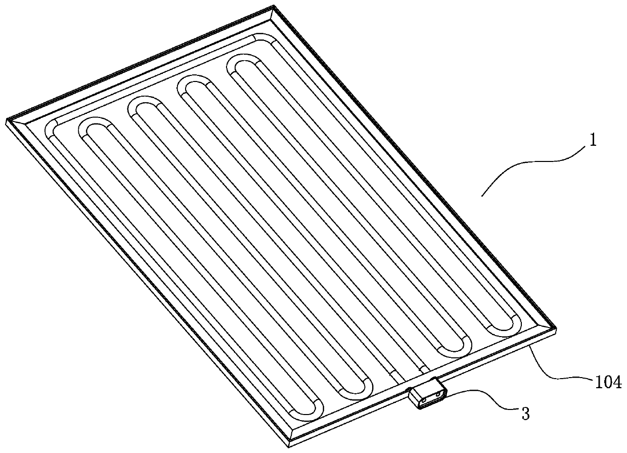
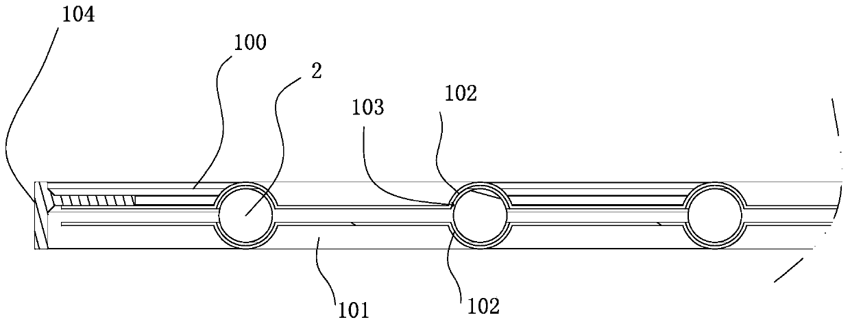
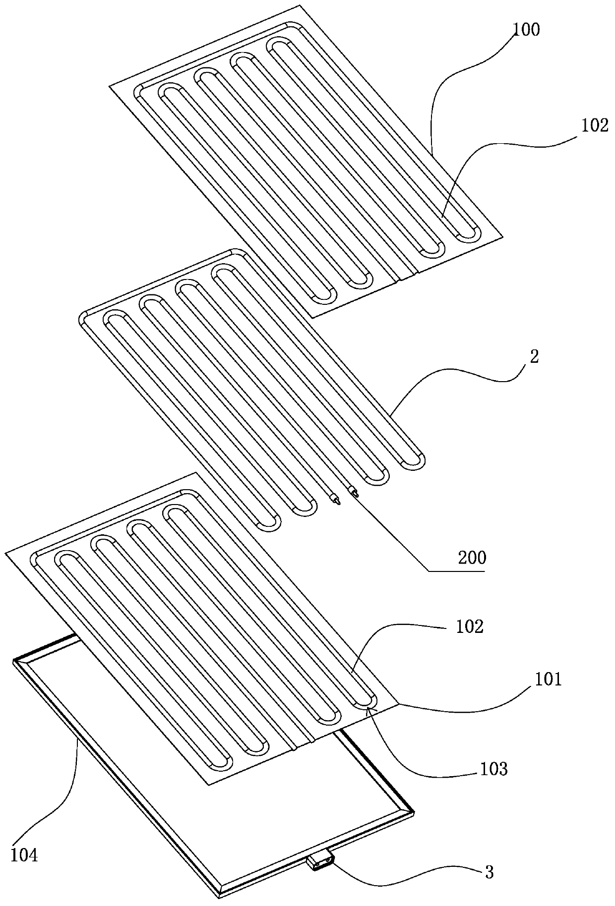
[0045] See Figure 1 ~ Figure 3 As shown, a heating module 1 of the present invention includes a heating element 2 and has a conductive end 200; the heating element 2 is a prior art product, which can be a heating wire made of nickel-chromium alloy wire or a heating wire. Diaphragm, PTC heating element, etc., whose conductive end 200 is connected to the heating element to generate heat when the heating element is energized. Two oppositely arranged heat sinks: a first heat sink 100 and a second heat sink 101. The first heat sink 100 and the second heat sink 101 are made of aluminum plates with good thermal conductivity. The heat sink material can also be Mica board, gypsum board, etc., which are used for heat dissipation. The opposite inner side walls of the first heat sink 100 and the second heat sink 101 are both provided with recessed accommodatin...


PUM


Abstract

The invention discloses a heating module, a heating module set and an electric heating radiator. The heating module comprises a heating body, a first radiating fin and a second radiating fin which areoppositely arranged and a connection plug, wherein the heating body is provided with a conductive end; the opposite inner side walls of the first radiating fin and the second radiating fin are provided with concave containing grooves, the containing grooves in the first radiating fin and the second radiating fin form a containing channel, the heating body is arranged in the containing channel, and the outer side wall of the heating body is tightly attached to the inner wall of the containing channel; and the connection plug is arranged on the outer sides of the radiating fins and is electrically connected with the conductive end of the heating body and is used for connecting a power plug to get electricity. The heating module, the heating module set and the electric heating radiator are low in heating temperature, high in safety, fast in radiating speed, high in radiating efficiency, low in energy consumption, energy-saving and environment-protecting.

Description

Technical field [0001] The invention relates to the technical field of heating and ventilation equipment, in particular to a heating module, a heating module and an electric radiator. Background technique [0002] Electric radiator, also called electric heater, is a kind of heating equipment mainly used for heating. It is mainly used in the cold northern regions in winter and has the function of keeping the room warm. The structure of an electric radiator in the prior art generally includes a shell and an electric heating tube arranged in the shell. The electric heating tube is provided with radiating fins. The heat generated by the electric heating tube is heated by the radiating fin to heat the room. . For example, the State Intellectual Property Office published a patent application with an authorized publication number CN206459250U and a name for an electric radiator. Its structure includes a shell, a plurality of strip-shaped CNT heaters placed side by side in the shell, an...

Claims


Application Information

Patent Timeline
IPC IPC(8): F24D13/00F24D19/00F24D19/06F24D19/08F24D19/10
CPCF24D13/00F24D19/00F24D19/06F24D19/065F24D19/067F24D19/068F24D19/08F24D19/1096
Inventor 尹向红杨明徐增王承勇
Owner 瑞弗德(宁波)暖通科技有限责任公司
Why Eureka
Try Eureka