Device for testing debonding strength between stringer and skin

A technology of strength testing and skinning, which is applied to measuring devices, strength characteristics, and mechanical devices, etc., can solve problems such as waste of resources, poor applicability, and low device reuse rate, and achieve the effect of improving applicability and maintaining stability.

Pending Publication Date: 2020-01-03
DALIAN UNIV OF TECH
View PDF0 Cites 1 Cited by
  • Summary
  • Abstract
  • Description
  • Claims
  • Application Information

AI Technical Summary

Problems solved by technology

[0003] However, due to the small area of ​​the connection between the skin and the stringer compared to the area of ​​the entire test piece, it is difficult to measure the stringer / skin debonding strength using traditional methods
In addition, some currently existing devices for measuring the debonding strength of stringers / skins are only suitable for test pieces with a relatively fixed size, which makes the device reusable and poor in applicability, resulting in a waste of resources
Moreover, in the process of measuring the debonding strength of the stringer / skin, the distance between the support point and the loading point has a great influence on the success rate of the test: if the distance is too large, the stringer / skin may not be debonded, resulting in failure of the test; if the distance is too small May cause failure prior to skin stringer / skin debonding, also cause test failure

Method used


Image

  • Device for testing debonding strength between stringer and skin
  • Device for testing debonding strength between stringer and skin
  • Device for testing debonding strength between stringer and skin

Examples


Embodiment Construction

[0018] The patented system of the present invention will be further described below with reference to the accompanying drawings, in which the same reference numerals represent the same elements throughout. It should be understood that the orientations or positional relationships indicated by the terms "above", "below", "left", "right", "vertical", etc. are based on the orientations or positional relationships shown in the drawings, and are only for convenience of description The present invention and simplified description do not indicate that the referred elements must have a specific orientation and configuration.

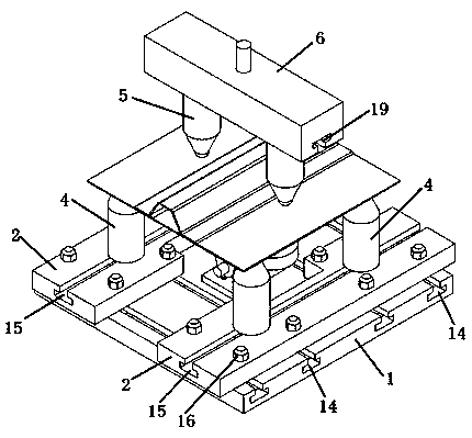
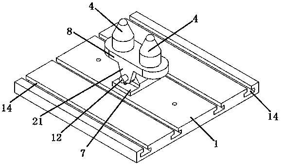
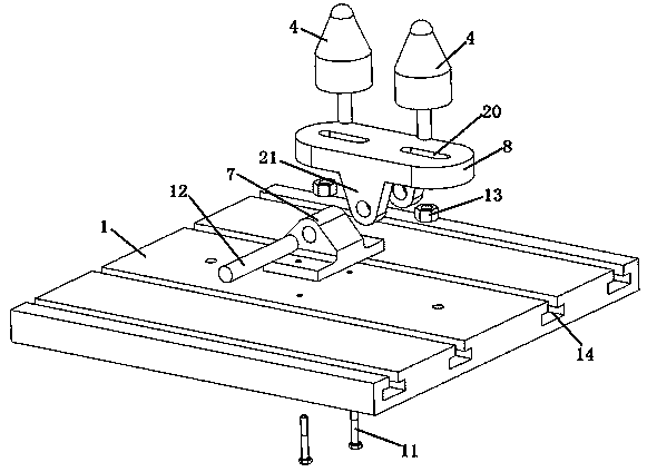
[0019] Figure 1 to Figure 6 A set of stringer-skin debonding strength testing device is shown. It includes a fixed bottom plate 1, a slide plate 2, a four-corner support 3, an intermediate support 4, a loading support 5, a loading head 6, a fixed hinge support 7, a balance hinge support 8, a slide block 9, slide plate fixing bolts and nuts 10, a hinge Support ...


PUM


Abstract

A device for testing the debonding strength between a stringer and a skin belongs to the field of mechanical tests of stiffened wall plates in aviation and civil ships. The device is characterized inthat: load is applied above the skin at two sides of a rib through a point loading mode, and point support is applied below a bonding part between the stringer and the skin through a middle strut to promote stripping load to be generated between a flange of a stiffened plate stringer and the skin; one point support is applied to each of four positions of a test piece to maintain the balance of thetest piece, and the middle strut is arranged on a hinged support, so that the load can be automatically balanced and adjusted in the loading process; the device adopts a sliding plate component and aslotting mode in the device, and realizes that the distance between two loading points and the distance between supporting points are continuously adjustable; the device can be applied to the debonding strength of a composite material or a welded stiffened wall plate structure, can be applied to interface strength tests under different sizes and loads, and ensures the reutilization of a clamp.

Description

technical field [0001] The invention relates to a set of testing devices for debonding strength of long trusses and skins, which belongs to the field of mechanical testing of reinforced wall plates in aviation and civil ships. Background technique [0002] In order to reduce the weight of the composite reinforced panel structure and improve the bearing capacity of the aircraft, the design of modern aircraft usually allows the composite panel to buckle before the ultimate load, and in order to further tap the potential of the composite aircraft, the composite panel is allowed Buckling before limiting loads has come into view. When the panel is in the post-buckling state, the local deformation of the stringer or the skin causes a large "peeling stress" on the stringer / skin interface, causing debonding between the stringer and the skin. Therefore, the research on the problem of stringer / skin debonding has become a difficult problem that must be overcome in the post-buckling de...

Claims


Application Information

Patent Timeline
Patent Type & Authority Applications(China)
IPC IPC(8): G01N19/04G01N3/20G01N3/24G01N3/04G01N3/02
CPCG01N3/02G01N3/04G01N3/20G01N3/24G01N19/04G01N2203/0023G01N2203/0025G01N2203/0091
Inventor 白瑞祥郭振飞邹建超刘军军雷振坤刘达
Owner DALIAN UNIV OF TECH
Why Eureka
Try Eureka