
Welding method of concentric launching cylinder

A welding method and technology of a launch tube, applied in welding equipment, welding equipment, auxiliary welding equipment, etc., to achieve the effects of increasing overall structural rigidity, high structural strength, and reducing dimensional tolerances

Active Publication Date: 2021-07-30
SHANGHAI INST OF ELECTROMECHANICAL ENG
View PDF14 Cites 0 Cited by
  • Summary
  • Abstract
  • Description
  • Claims
  • Application Information

AI Technical Summary

Problems solved by technology

This invention patent is for thick arm steel cylinders, and is not suitable for butt joints with deformed parts

Method used


Image

  • Welding method of concentric launching cylinder
  • Welding method of concentric launching cylinder
  • Welding method of concentric launching cylinder

Examples


Embodiment Construction

[0043] The present invention will be described in detail below in conjunction with specific embodiments. The following examples will help those skilled in the art to further understand the present invention, but do not limit the present invention in any form. It should be noted that those skilled in the art can make several changes and improvements without departing from the concept of the present invention. These all belong to the protection scope of the present invention.

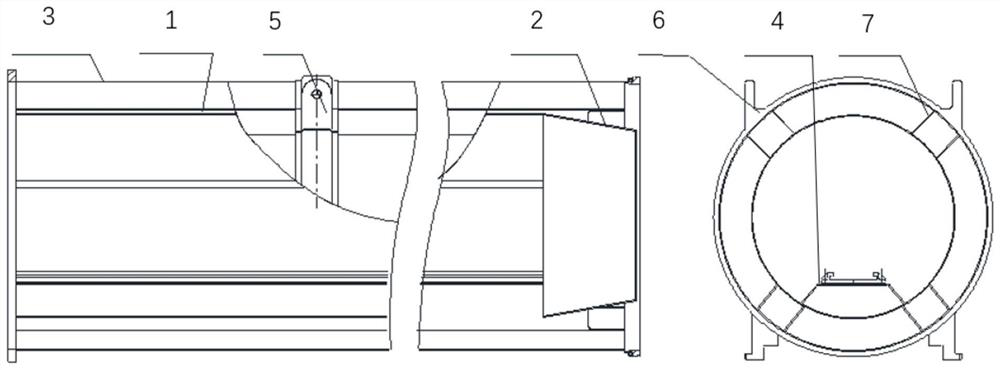
[0044] The invention provides a welding method for concentric launch cylinders, wherein the main structural components of the concentric launch cylinders include an inner cylinder 1, a shrinkage section 2, an outer cylinder 3, a rail seat 4, a hoop 5, and a flange 6 As well as the guide rails etc. placed on the guide rail seat, the shrinkage section 2 is a tapered cylinder structure, and the following method steps are used to make the launch cylinder cylinder for the above-mentioned structural parts:

...


PUM


Abstract

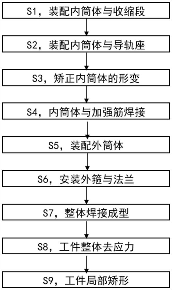
The invention relates to a welding method of a concentric launching cylinder in the field of welding deformation control, comprising the following steps: S1, assembling the inner cylinder and the shrinkage section; S2, assembling the inner cylinder and the guide rail seat; S3, correcting the inner cylinder Deformation; S4, welding of inner cylinder and rib; S5, assembly of outer cylinder; S6, installation of outer hoop and flange; S7, overall welding and forming; S8, overall stress relief of the workpiece; S9, partial orthopedics of the workpiece. In the present invention, various toolings are used together in the overall welding process of the concentric launching cylinder, so that the parts of the concentric launching cylinder can be spot welded and positioned in advance, and then the welding links in the process are reduced to the greatest extent, reaching almost one time. The technical effect of permanent integral molding can control the welding deformation of the concentric launching cylinder with high precision, and the inner cylinder and guide rail seat do not require post-welding machining, which greatly reduces production costs.

Description

technical field [0001] The invention relates to the field of welding deformation control, in particular to a method for welding concentric emitting cylinders. Background technique [0002] As a missile launcher, the concentric launcher is mainly used for missile transportation, storage and launch. The main structure of the concentric launching tube is the tube body, the guide rail, and the front and rear end covers. The concentric launching cylinder body is composed of an inner cylinder body, a contraction section, an outer cylinder body, a reinforcing rib, a guide rail seat, a flange, and an outer hoop. The inner cylinder is a cylinder; the shrinkage section is a cone; the outer cylinder is a plurality of circular arc plates; the ribs are grooved parts, wherein the ribs of the ribs are arc-shaped, and the outer diameter of the ribs is consistent with the outer diameter of the outer cylinder; The appearance of the rail seat is a trapezoidal groove; the outer hoop is a ring...

Claims


Application Information

Patent Timeline
Patent Type & Authority Patents(China)
IPC IPC(8): B23K31/02B23K37/04B23K37/00
CPCB23K31/02B23K37/00B23K37/04
Inventor 刘广宋伟张保刚刘龙涛俞刘建周波华张宏程王冠坤涂静
Owner SHANGHAI INST OF ELECTROMECHANICAL ENG
Learn More