Low-loss optical fiber drawing system and drawing method thereof

A low-loss, optical fiber technology, applied in glass manufacturing equipment, manufacturing tools, etc., can solve the problems of different positions of structural relaxation temperature, increase of optical fiber surface relaxation time, influence of optical fiber strength, etc., to improve internal defects, reduce Fiber loss and the effect of reducing fiber loss

Pending Publication Date: 2020-01-07
远东通讯有限公司
View PDF0 Cites 0 Cited by
  • Summary
  • Abstract
  • Description
  • Claims
  • Application Information

AI Technical Summary

Problems solved by technology

At present, the most important thing is to use thermal annealing to increase the relaxation time of the fiber surface, release the stress inside the fiber, and reduce structural defects. However, different types of fibers (with different dopant contents) have different structural relaxation temperatures; different The drawing degree and the position where the structure relaxation temperature is reached are also different.
Another common optical fiber annealing process adopts water vapor heat treatment. The optical fiber manufactured in this way is coated with a coating protective material without dehydration treatment. Internal diffusion will not only affect the attenuation of the fiber, but also affect the strength of the fiber

Method used


Image

  • Low-loss optical fiber drawing system and drawing method thereof
  • Low-loss optical fiber drawing system and drawing method thereof
  • Low-loss optical fiber drawing system and drawing method thereof

Examples


Embodiment 1

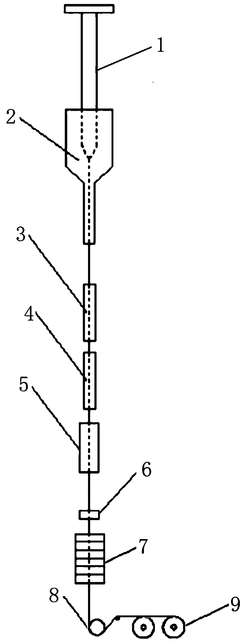
[0039] Such as figure 1 and figure 2The low-loss optical fiber drawing system shown includes a preform feeding device 1, a drawing furnace 2, a steam annealing device 3, a dehydration device 4, a cooling pipe 5, and a coater, which are sequentially arranged on the drawing tower from top to bottom. 6 and curing device 7, as well as traction device 8 and the take-up device 9 located at one side of traction device 8.

[0040] Two sets of three-degree-of-freedom mobile platforms are installed on the drawing tower. The three-degree-of-freedom mobile platforms include X-axis drive mechanisms, Y-axis drive mechanisms and Z-axis drive mechanisms. The steam annealing device 3 and the dehydration device 4 are respectively installed on two sets On the X-axis drive mechanism of the three-degree-of-freedom mobile platform, the X-axis drive mechanism is installed on the Y-axis drive mechanism, the Y-axis drive mechanism is installed on the Z-axis drive mechanism, and the Z-axis drive mech...

Embodiment 2

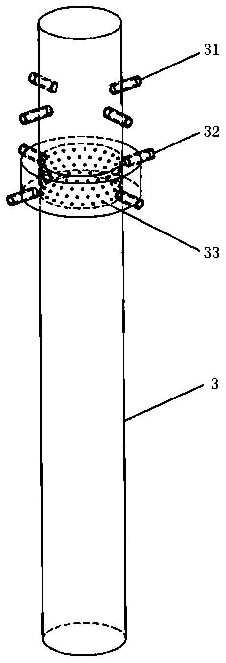
[0060] This embodiment is similar in structure to the low-loss optical fiber drawing system of Embodiment 1, except that the water vapor annealing device 3 uses microwaves to generate water vapor. In addition, as image 3 As shown, the water vapor annealing device 3 of embodiment 2 adds a double-layer cavity on the basis of embodiment 1, which is located at the outer peripheral position of the water vapor inlet 32, and the double-layer cavities are communicated through uniformly distributed small holes 33, reducing the The air pressure when the water vapor enters the cylindrical annealing device is reduced, thereby reducing the disturbance of the optical fiber in the cylindrical annealing device, thereby improving the coating quality. In order to prevent water vapor from condensing in the pipe, double-layer pipes can be used, and the outer layer is filled with circulating hot water to keep the glass tube at a certain temperature, effectively preventing water vapor from condensi...


PUM

PropertyMeasurementUnit
Lengthaaaaaaaaaa
Diameteraaaaaaaaaa

Abstract

The invention discloses a low-loss optical fiber drawing system and a drawing method thereof. The low-loss optical fiber drawing system comprises a preform feeding device, a drawing furnace, a water vapor annealing device, a dehydration device, a cooling pipe coater, a curing device,a traction device and a take-up devicearranged on one side of the traction device, wherein the preform feeding device, the drawing furnace, the water vapor annealing device, the dehydration device, the cooling pipe coater and the curing device are sequentially arranged on a drawing tower frame from top to bottom, and the heights and the horizontal positions of the water vapor annealing device and the dehydration device can be adjusted, so that the water vapor annealing device capable of being arranged at different positions according to different optical fiber types and different optical fiber wire drawing speeds, and the drawing method thereof are achieved. According to the invention, by additionally arranging the dehydration device, the residual water in grids is removed, so that the internal structure of the optical fiber is improved so as to reduce the loss of the optical fibers.

Description

technical field [0001] The invention relates to a low-loss optical fiber drawing system and a drawing method thereof. Background technique [0002] With the rapid development of communication technology, the use of optical fiber in communication is increasing day by day. In the process of long-distance transmission, due to the high loss of traditional optical fiber, it is necessary to increase the signal strength by adding relay stations at a certain distance, and the price of relay stations Relatively high, which has given rise to the demand for low-loss optical fibers for optical communications. [0003] Optical fiber loss is mainly divided into intrinsic loss and manufacturing loss. The intrinsic loss of optical fiber is the inherent loss of optical fiber and cannot be avoided. The manufacturing loss of optical fiber is mainly caused by absorption loss and structural defects of impurities introduced during the manufacturing process. Impurity absorption is mainly due to...

Claims


Application Information

Patent Timeline
IPC IPC(8): C03B37/10C03B37/025C03C25/12C03C25/64
CPCC03B37/10C03B37/025C03C25/12C03C25/64
Inventor 李鑫鑫向德成段宏峰吴煜蒋宇星丁迎霞
Owner 远东通讯有限公司
Why Eureka
Try Eureka