Prefabricated Weak Connection Structure of Reinforced Concrete Coupling Beam and Its Construction Method

A reinforced concrete and construction method technology, applied in the direction of building components, building structures, walls, etc., can solve the problems of increasing component rigidity, weakening bending bearing capacity, and construction difficulties, and achieve the effect of reducing friction and preventing concrete damage

Active Publication Date: 2021-01-05
TONGJI UNIV ARCHITECTURAL DESIGN INST GRP CO LTD
View PDF9 Cites 0 Cited by
  • Summary
  • Abstract
  • Description
  • Claims
  • Application Information

AI Technical Summary

Problems solved by technology

The first method can be adopted to form steel concrete coupling beams, increase diagonal hidden braces, increase the height of coupling beams, etc., but these methods will often further increase the stiffness of components, further attract greater shear force, and form Vicious circle, extremely uneconomical and difficult to construct
The second method can take measures such as joint beam splitting and directly reducing the stiffness of the coupling beam when calculating the earthquake action; although the joint beam splitting can effectively weaken the stiffness of the coupling beam, its flexural bearing capacity will also be weakened And the construction is difficult
[0005] Coupling beams are generally damaged during earthquakes, and there are certain difficulties in the repair or replacement of coupling beams integrated with shear walls after earthquakes

Method used


Image

  • Prefabricated Weak Connection Structure of Reinforced Concrete Coupling Beam and Its Construction Method
  • Prefabricated Weak Connection Structure of Reinforced Concrete Coupling Beam and Its Construction Method
  • Prefabricated Weak Connection Structure of Reinforced Concrete Coupling Beam and Its Construction Method

Examples


Embodiment Construction

[0036] The technical solution of the present invention will be further described below in conjunction with the accompanying drawings.

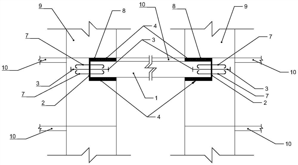
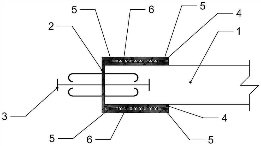
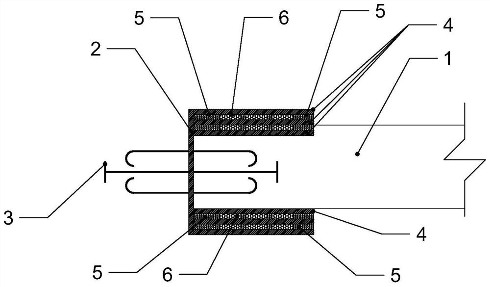
[0037] Such as figure 1 and figure 2 As shown, the present invention sets a prefabricated weak connection structure of reinforced concrete connecting beam between the shear wall 9 and the connecting beam 1. The prefabricated weak connection structure includes an end steel plate 2, an anti-falling rod 3, an anti-local pressure steel plate 4, Elastic layer 5, isolation layer 6 and anchor bars 7. Floor slabs 10 are also connected to the shear walls 9 and the connecting beams 1 of the present invention.

[0038] The end steel plate 2 of the present invention is arranged at the end of the connecting beam 1, and the anti-falling rods 3 are arranged symmetrically on both sides of the end steel plate 2. One side anti-falling rod 3 extends into the inside of the connecting beam 1, and the other side The anti-falling bar 3 extends into the shear wal...


PUM


Abstract

The invention discloses a prefabricated weak connection structure of a reinforced concrete coupling beam and a construction method thereof. The prefabricated weak connection structure comprises an endsteel plate positioned at the connecting beam end part, anti-off rods which are positioned on two side surfaces of the end steel plate and are symmetrically arranged, and at least two local-pressure-preventive steel plates which are positioned at the upper part / lower part of a connecting beam and are vertically arranged at intervals relative to the end steel plate, wherein an elastic layer and an isolating layer are transversely arranged at intervals in a gap between every two local-pressure-preventive steel plates. The structure can reliably transmit axial force, shearing force and a smallamount of bending moment under the action of earthquake, and reduce the shearing force caused by the bending moment.

Description

technical field [0001] The invention relates to a concrete coupling beam structure, in particular to a prefabricated weak connection structure of a reinforced concrete coupling beam. Background technique [0002] Coupling beams refer to beams that connect wall piers to wall piers in the shear wall structure and frame-shear wall structure, and are connected within the plane of the wall piers. Coupling beams generally have the characteristics of small span, large cross-section, and high stiffness of the wall connected to the coupling beam. Under the action of an earthquake, the bending moment at the end of the coupling beam is very large, and its span is small, which leads to the failure of the coupling beam end. The shear force is very large. [0003] In the seismic design, in order to resist the huge internal force of the coupling beam caused by the earthquake, two measures are taken: (1) increase the resistance of the component so that the component can withstand the huge ...

Claims


Application Information

Patent Timeline
Patent Type & Authority Patents(China)
IPC IPC(8): E04B1/98E04H9/02E04B1/21E04B2/64
CPCE04B1/215E04B1/98E04B2/64E04H9/021E04H9/022
Inventor 毛范燊
Owner TONGJI UNIV ARCHITECTURAL DESIGN INST GRP CO LTD
Why Eureka
Try Eureka