Convenient and fast industrial furnace

An industrial furnace and convenient technology, applied in furnaces, muffle furnaces, cooking furnaces, etc., can solve the problems of high temperature outside the furnace body, unfavorable energy saving, large heat loss, etc., to improve thermal efficiency and reduce heat loss. , the effect of saving energy

Inactive Publication Date: 2020-01-07
浙江万能达炉业有限公司
View PDF1 Cites 2 Cited by
  • Summary
  • Abstract
  • Description
  • Claims
  • Application Information

AI Technical Summary

Problems solved by technology

[0004] The present invention provides a portable industrial furnace, which can effectively solve the problem that the temperature outside the furnace body is high during use, the heat loss is relatively large, and more electric energy is consumed during heating, which is not conducive to energy conservation. question

Method used


Image

  • Convenient and fast industrial furnace
  • Convenient and fast industrial furnace
  • Convenient and fast industrial furnace

Examples


Embodiment

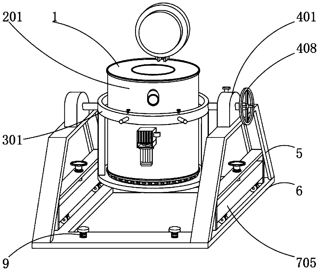
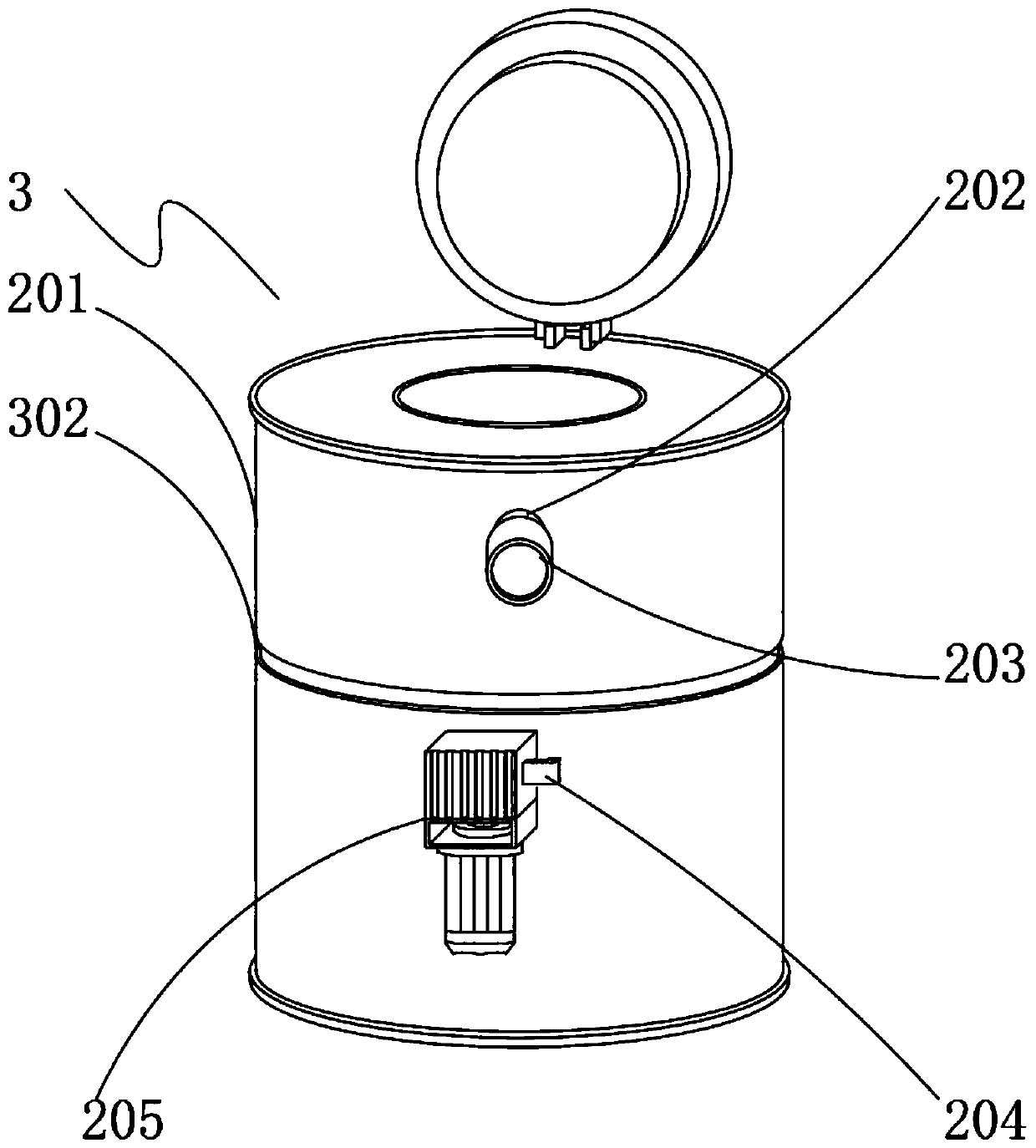
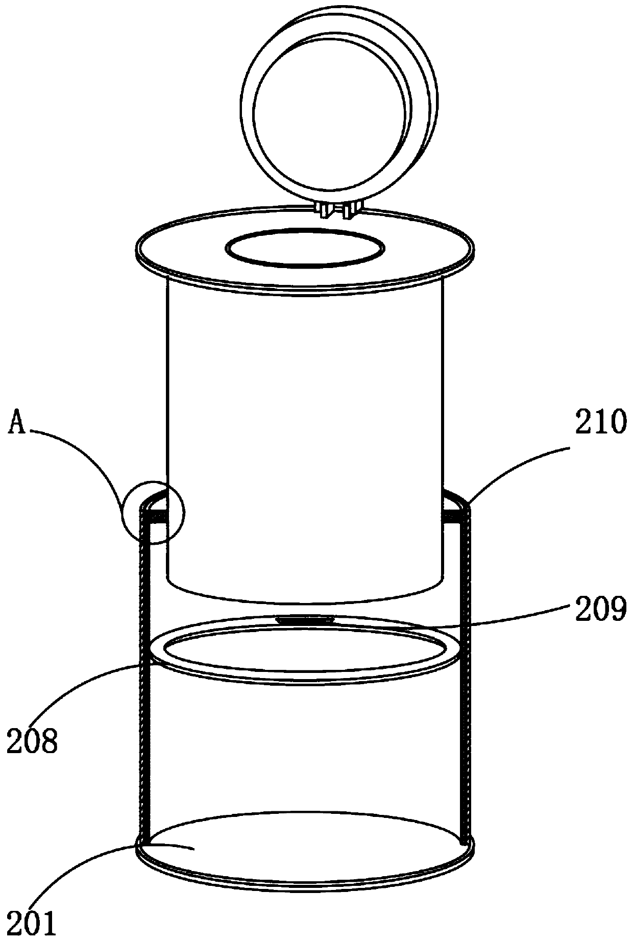
[0044] Example: such as Figure 1-8 As shown, the present invention provides a technical solution, a portable industrial furnace, including a furnace body 1, a heat preservation component 2 is arranged on the outside of the furnace body 1, and the heat preservation component 2 includes an outer cylinder 201, an air inlet pipe 202, an end cover 203, a pump Air pipe 204, vacuum pump 205, glass cylinder 206, silver-plated film 207, separation ring 208, communication port 209 and sealing ring 210;

[0045] The outer cylinder 201 is fixedly socketed on the outer side of the furnace body 1, and an air intake pipe 202 is installed through the upper front of the outer cylinder 201. One end of the air intake pipe 202 is threaded with an end cover 203, and an exhaust pipe 204 is installed through the lower front of the outer cylinder 201. One end of the exhaust pipe 204 is connected with a vacuum pump 205, and a glass cylinder 206 is placed inside the outer cylinder 201. The air inlet p...


PUM


Abstract

The invention discloses a convenient and fast industrial furnace. A heat preservation assembly is arranged on the outer side of a furnace body. One end of a gas extracting pipe is connected with a vacuum pump. A silver-plated film is evenly arranged on the outer side of a glass barrel. A supporting assembly is installed on the outer side of the furnace body. A positioning groove is formed in the position, corresponding to the position of a positioning circle, of the furnace body. A rolling wheel is welded to one end of each positioning rod. An adjustment assembly is installed on the middle portion of a rotating shaft. A positioning ring is placed in an adjustment groove. A guide opening is formed in the position, corresponding to a regulation rod, on the top face of a supporting base. An adjustment wheel is welded to the end, close to a ratchet wheel, of the rotating shaft. Before the convenient and fast industrial furnace conducts heating, air between the glass barrel and the furnacebody is completely pumped out through a vacuum pump, and the portion between the glass barrel and the furnace body is kept in the vacuum state; thermal conductivity of vacuum and the glass barrel is poor, thermal radiation is reflected back by the silver-plated film through specular reflection, the heat loss is reduced, the thermal efficiency is improved, energy is saved, and the aim of energy conservation is achieved; and the furnace body can be inclined, the movement range of the furnace body is wide, and the inner portion and the outer portion of the furnace body can be conveniently cleaned.

Description

technical field [0001] The invention relates to the technical field of industrial furnaces, in particular to a portable industrial furnace. Background technique [0002] Industrial furnaces are thermal equipment used in industrial production to heat materials or workpieces by using the heat converted from fuel combustion or electric energy. They are divided into two types according to the heating method: one is the flame furnace, which uses solid, liquid or gas fuel in The combustion heat in the furnace heats the workpiece; the second type is the electric furnace, which converts electrical energy into heat for heating in the furnace, and is widely used. [0003] In the patent with the publication number CN102927584B, "a plasma industrial furnace" is mentioned, which includes a heating device, a primary plasma generator and a superimposed plasma expansion generator. The industrial furnace has a simple structure, high combustion efficiency, and low cost of use. However, durin...

Claims


Application Information

Patent Timeline
Patent Type & Authority Applications(China)
IPC IPC(8): F27B5/05F27B5/06
CPCF27B5/04F27B5/06F27D2099/0098
Inventor 朱卫福陆乾明施建国
Owner 浙江万能达炉业有限公司
Why Eureka
Try Eureka