
A method for monitoring the combustion field of an aero-engine with a space-access optical frequency comb system

An aero-engine and optical frequency comb technology, which is applied in the field of laser technology and combustion diagnosis, and the space-access optical frequency comb system monitors the field of aero-engine combustion field, which can solve the problem of low spectral resolution, elevated and unstable combustion field instantaneous temperature Problems such as measurement ability, to achieve the effect of low cost and simple structure

Active Publication Date: 2021-01-15
BEIHANG UNIV
View PDF8 Cites 0 Cited by
  • Summary
  • Abstract
  • Description
  • Claims
  • Application Information

AI Technical Summary

Problems solved by technology

However, traditional absorption spectroscopy measurement devices, such as prisms, gratings, Fourier transform spectrometers and single-frequency lasers, have low spectral resolution, low detection sensitivity, low frequency measurement accuracy and measurement speed, and are not suitable for unstable combustion fields. The instantaneous temperature measurement capability needs to be improved
[0005] Based on the above background, the existing method of using laser absorption spectroscopy to monitor the combustion field of aero-engines needs to be further optimized

Method used


Image

  • A method for monitoring the combustion field of an aero-engine with a space-access optical frequency comb system
  • A method for monitoring the combustion field of an aero-engine with a space-access optical frequency comb system
  • A method for monitoring the combustion field of an aero-engine with a space-access optical frequency comb system

Examples


Embodiment Construction

[0033] In order to make the purpose, technical solutions and advantages of the embodiments of the present invention clearer, the technical solutions of the present invention will be clearly and completely described below in conjunction with the accompanying drawings. Obviously, the described embodiments are part of the embodiments of the present invention, not all of them. the embodiment. Based on the embodiments of the present invention, all other embodiments obtained by persons of ordinary skill in the art without making creative efforts belong to the protection scope of the present invention.

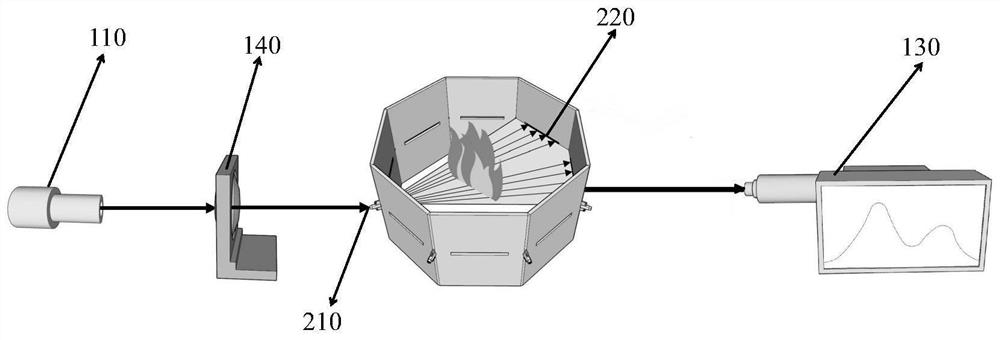
[0034] The invention provides a method for monitoring the combustion field of an aero-engine with a space-access type optical frequency comb system, which has the advantages of simple structure, high integrability, convenient operation, and low cost. Changes in gas concentration.

[0035] In order to facilitate the understanding of this embodiment, firstly, a method for monitoring t...


PUM


Abstract

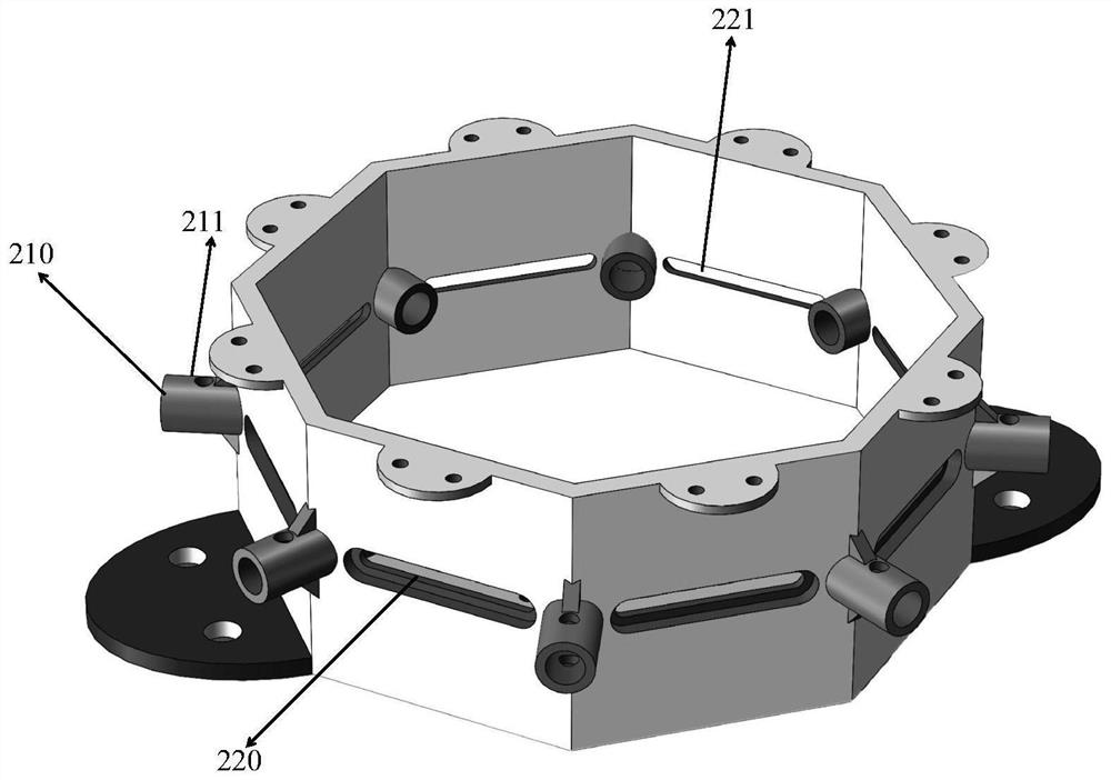
The invention provides a method for monitoring an aero-engine combustion field by a space access type optical frequency comb system. The method is characterized in that an optical frequency comb passes through a beam splitter to obtain two beams of optical frequency combs; one beam is inputted into a spectrum analysis module and the other beam is inputted into a combustion chamber monitoring device after a collimating lens; and an obtained output signal is connected with the spectrum analysis module. The optical frequency comb serving as signal light passes through the combustion chamber to obtain an absorption spectrum signal; the combustion chamber monitoring device is used for acquiring multiple paths of acquisition signals; the spectral analysis module is used for carrying out real-time comparison and analysis on the multiple paths of absorption spectrum signals and spectral signals of the optical frequency comb to obtain change conditions of various parameters of the gas componentconcentration in the aero-engine combustion chamber. According to the invention, the structure is compact and the method is simple. With the spatial light structure of the system, the difficulty caused by contact monitoring is eliminated and the cost of the system is lowered; and the system is convenient to operate. Meanwhile, the combustion field of the aero-engine can be rapidly and accuratelymonitored.

Description

[0001] (1) Technical field [0002] The invention relates to the field of laser technology and the field of combustion diagnosis, in particular to the technical field of monitoring an aeroengine combustion field by a space-access type optical frequency comb system. [0003] (2) Background technology [0004] The aero-engine combustor is one of the core components of an aero-engine. When the aircraft is working, complex reactions will occur in the combustion chamber of the aero-engine, and it is difficult to accurately describe the actual combustion process with computational fluid dynamics. Accurate measurement of key parameters in the combustion process is necessary for effective combustion diagnosis techniques. According to the measured data, the structure of the aero-engine can be improved to obtain a high-performance aero-engine. Specifically, it is necessary to achieve reliable and accurate measurement of key parameters such as temperature, pressure, and gas component co...

Claims


Application Information

Patent Timeline
Patent Type & Authority Patents(China)
IPC IPC(8): G01M15/05
CPCG01M15/05
Inventor 付博徐立军张程宏李静陆哲睿尚策
Owner BEIHANG UNIV
Learn More