Supercharge Your Innovation With Domain-Expert AI Agents!

Gear rack feeding mechanism

A feeding mechanism, rack and pinion technology, applied in the direction of conveyor objects, metal processing equipment, feeding devices, etc., can solve the problems of high cost and single stroke

Inactive Publication Date: 2020-01-10
SHENHUA RAIL & FREIGHT WAGONS TRANSPORT
View PDF9 Cites 0 Cited by
  • Summary
  • Abstract
  • Description
  • Claims
  • Application Information

AI Technical Summary

Problems solved by technology

[0003] Based on this, it is necessary to provide a rack and pinion feeding mechanism for the problems of high cost or single stroke in the current automatic production line feeding mechanism

Method used


Image

  • Gear rack feeding mechanism
  • Gear rack feeding mechanism
  • Gear rack feeding mechanism

Examples


Embodiment 1

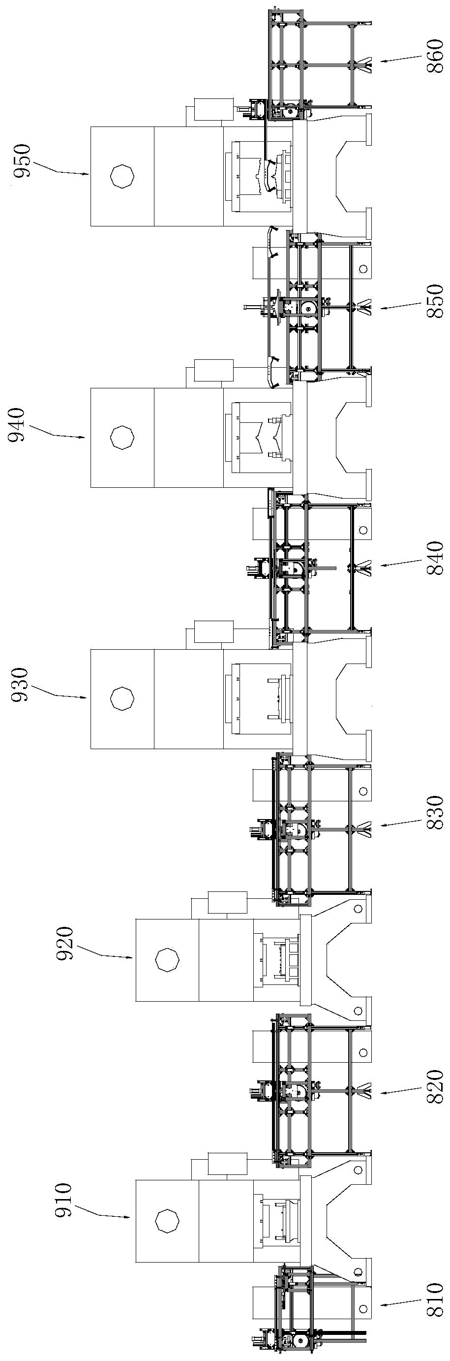
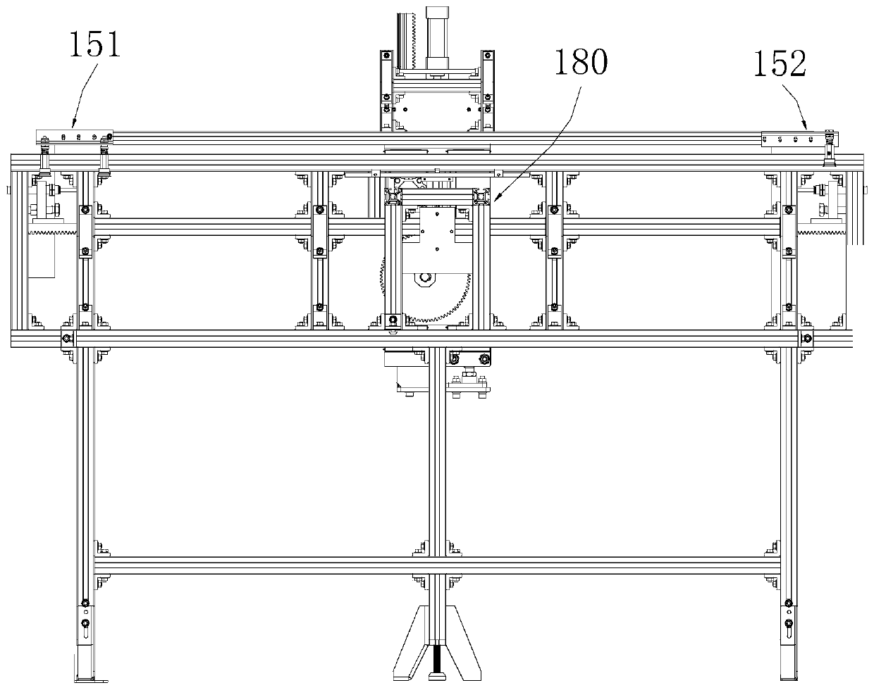
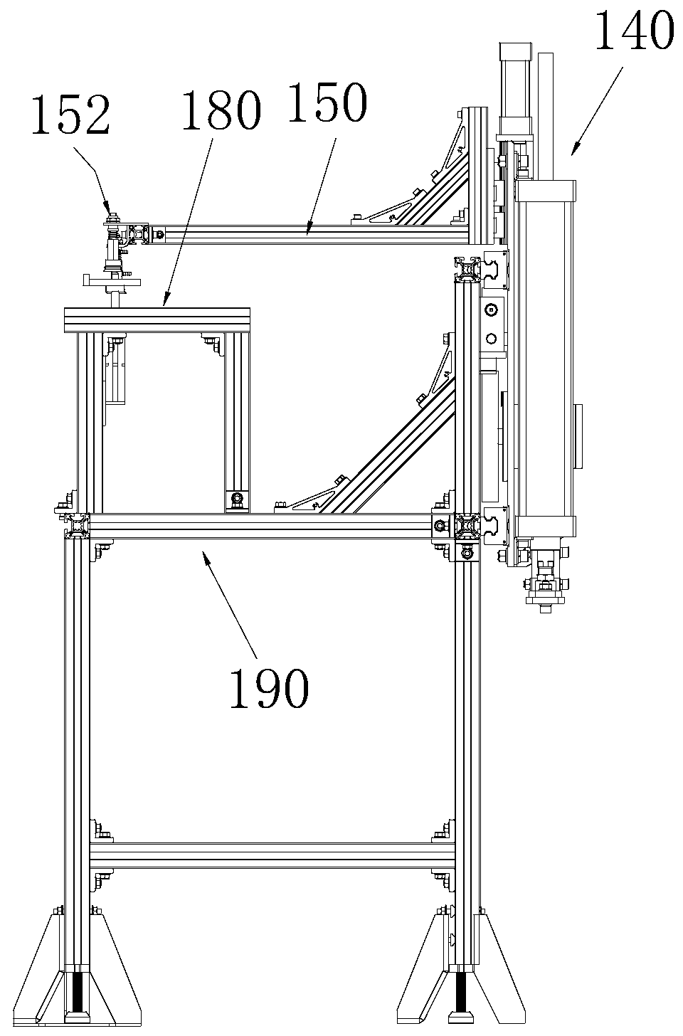
[0044] In this embodiment, a punch production line is provided, such as Figure 1 to Figure 4 As shown, it includes five punches from the first punch 910 to the fifth punch 950, and the first feeding mechanism 810 to the sixth feeding mechanism 860 are arranged at each two punches and the two ends of the entire punch production line, and each feeding mechanism applies The above-mentioned rack and pinion feeding mechanism 100 is used as a power mechanism. Rack and pinion feeding mechanism 100 comprises frame 190, sliding plate 140, driving rack 110, driven rack 120, duplex gear 130 and grabbing arm 150, and frame 190 is fixedly installed on the ground, and frame 190 is made of A frame structure made of aluminum profiles or other common profiles. The upper part of the frame 190 is made of a plurality of profiles into a rectangular frame. Slide rails are arranged on the two long sides of the rectangular frame. The sliding plate 140 can be moved through two sliders. Slidingly mou...

Embodiment 2

[0050] In this embodiment, due to the different processing procedures of the first punch to the fifth punch 950, the models and sizes of the first punch to the fifth punch 950 are different, resulting in different installation heights during workpiece processing, so the first feeding mechanism 810 to the fifth The height of the frame 190 of the rack and pinion feeding mechanism 100 among the six feeding mechanisms 860 is also adjusted accordingly. At the same time, in order to meet the workpiece handling between punching machines of different heights, compared with the first embodiment, no additional mechanism is added, but the profiles originally arranged horizontally in the frame 190 are changed to inclined ones, and the rest of the structure remains unchanged. When the second to the fifth feeding mechanism 850 for realizing workpiece transfer between punches of different heights are working, the second feeding mechanism 820 is used as an example, the height difference betwee...

Embodiment 3

[0053] For the punches of different heights in the second embodiment, in order to meet the workpiece handling between punches of different heights, the first handling assembly 151 and the second handling assembly 152 on the same grabbing arm 150 can be set to different heights, and the driven teeth Bar 120 is still set horizontally. The first handling assembly 151 is lower than the second handling assembly 15210cm in the horizontal direction, and this height difference can be realized by adding a connecting piece 210 between the first handling assembly 151 and the grabbing arm 150, as in the first handling assembly 151 A connection block with a thickness of 10cm is set between the grab arm 150, and the second handling assembly 152 is directly connected to the grab arm 150 to realize a height difference between the two; the left and right parts of the grab arm 150 can also be set as At different heights, the left and right parts are in a zigzag structure, forming a height diffe...


PUM

PropertyMeasurementUnit
Thicknessaaaaaaaaaa

Abstract

The invention provides a gear rack feeding mechanism. The mechanism comprises a driving rack, a driven rack, a duplex gear, a driving piece and a rack, wherein the duplex gear comprises a driving gearand a driven gear which can rotate coaxially at the same rotating speed, the driving gear meshes with the driving rack, the driven gear meshes with the driven rack, a carrying mechanism is further arranged, and the carrying mechanism carries a workpiece to a specified position under indirect driving of the driving piece. By adjusting the number of teeth and the modulus of the driving gear and thedriven gear, different drive ratios between the driving rack and the driven rack can be achieved, the driven rack is driven to move a designed length by utilizing the standard driving piece with a fixed stroke, due to the fact that the mechanism adopts normal fixed-stroke standard driving piece and the standard gear and rack, the cost is low, the stroke range of the fixed-stroke standard drivingpiece can be converted into the required stroke through the gear rack mechanism, and the stroke requirement of feeding between different machines is met.

Description

technical field [0001] The invention relates to the field of parts handling equipment, in particular to a rack and pinion feeding mechanism. Background technique [0002] With the rapid development of modern industry and the increasing social demand, and in order to reduce production costs, it is required that stamping can be produced quickly and efficiently. Therefore, it is required that the mold can be realized in the way of multi-station and automatic processing production line. The existing multi-station automatic processing production line needs to install an automatic feeder, or a mechanical clamp or a mechanical suction cup between multiple stations to realize the feeding transfer between each working step. The existing automatic feeding mechanism usually has Two ways: one is to use the servo motor to drive the linear module to achieve precise movement of each position, but the linear module is a precision mechanism, the investment cost is too high, and its daily ope...

Claims


Application Information

Patent Timeline
IPC IPC(8): B21D43/10B21D43/18B65G47/91
CPCB21D43/105B21D43/18B65G47/912B65G47/918
Inventor 苏军贾刚翟惠建井科
Owner SHENHUA RAIL & FREIGHT WAGONS TRANSPORT
Features
  • R&D
  • Intellectual Property
  • Life Sciences
  • Materials
  • Tech Scout
  • Unparalleled Data Quality
  • Higher Quality Content
  • 60% Fewer Hallucinations
Learn More