Supercharge Your Innovation With Domain-Expert AI Agents!

Gear crank drive of a bicycle

A technology for driving devices and bicycles, which is applied in wheel transmissions, rider drives, vehicle components, etc., and can solve the problems of battery mileage and driving performance, low efficiency, low torque density, etc.

Active Publication Date: 2019-01-29
ROBERT BOSCH GMBH
View PDF10 Cites 0 Cited by
  • Summary
  • Abstract
  • Description
  • Claims
  • Application Information

AI Technical Summary

Problems solved by technology

However, friction ring transmissions have low efficiencies due to the force transmission via frictional locking, which without motor support is detrimental to battery range and especially at speeds above 7 m / s (about 25 km / h). Significant impact on driving performance
[0004] A treadle bearing drive based on a spur gear transmission with an integrated shifting device (for example as described in DE 10 2010 051 727 A1 or EP 2 881 315 A2) has the disadvantage of a low torque density and the Shifting is not possible under load or only under partial load in lower gears
Furthermore, such a shifting device does not have an electromechanically actuated automatic gear selection
The solution as in WO 2013 / 160477 A1 has the disadvantage that the shifting does not take place without traction interruption

Method used


Image

  • Gear crank drive of a bicycle
  • Gear crank drive of a bicycle
  • Gear crank drive of a bicycle

Examples


Embodiment Construction

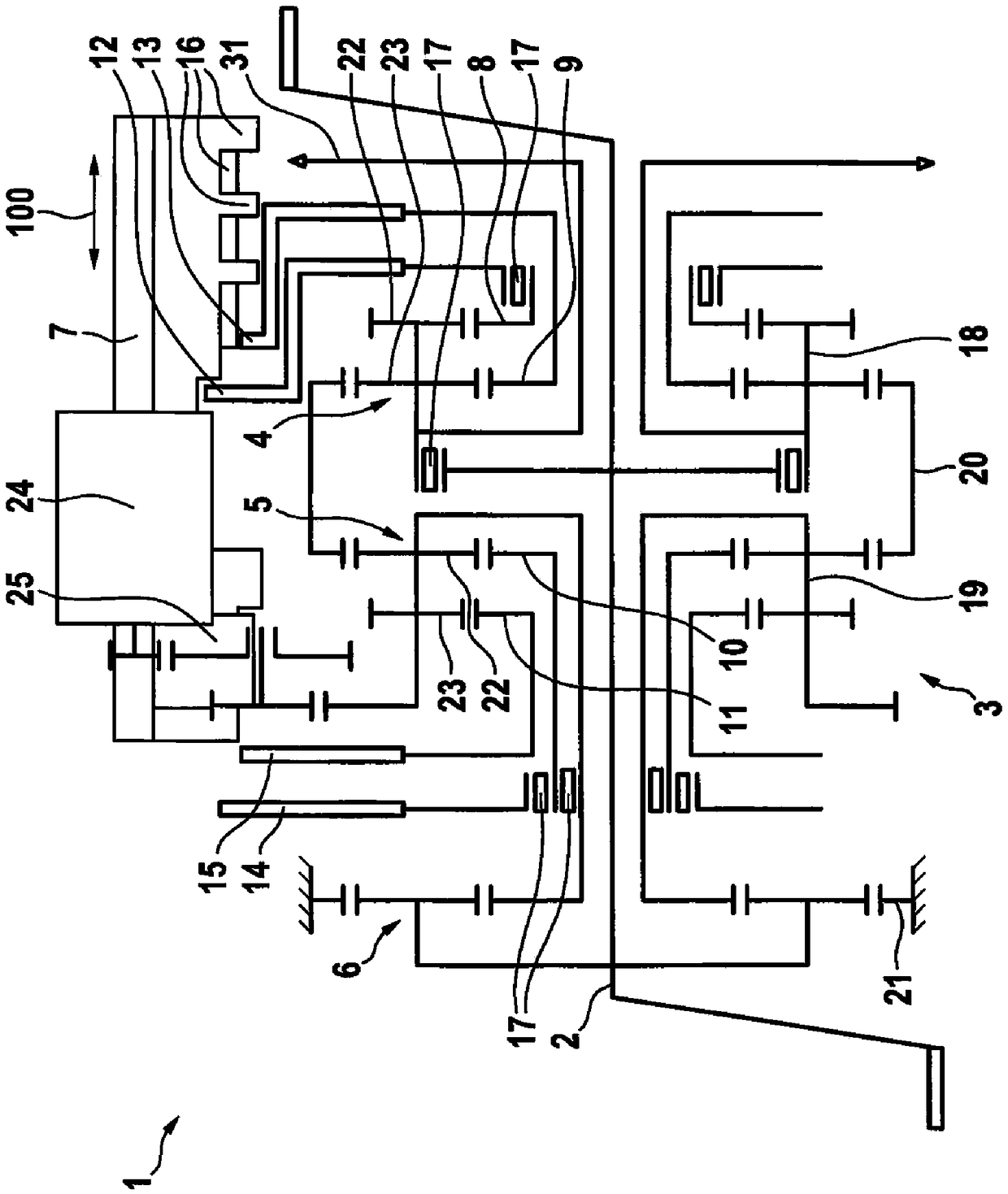
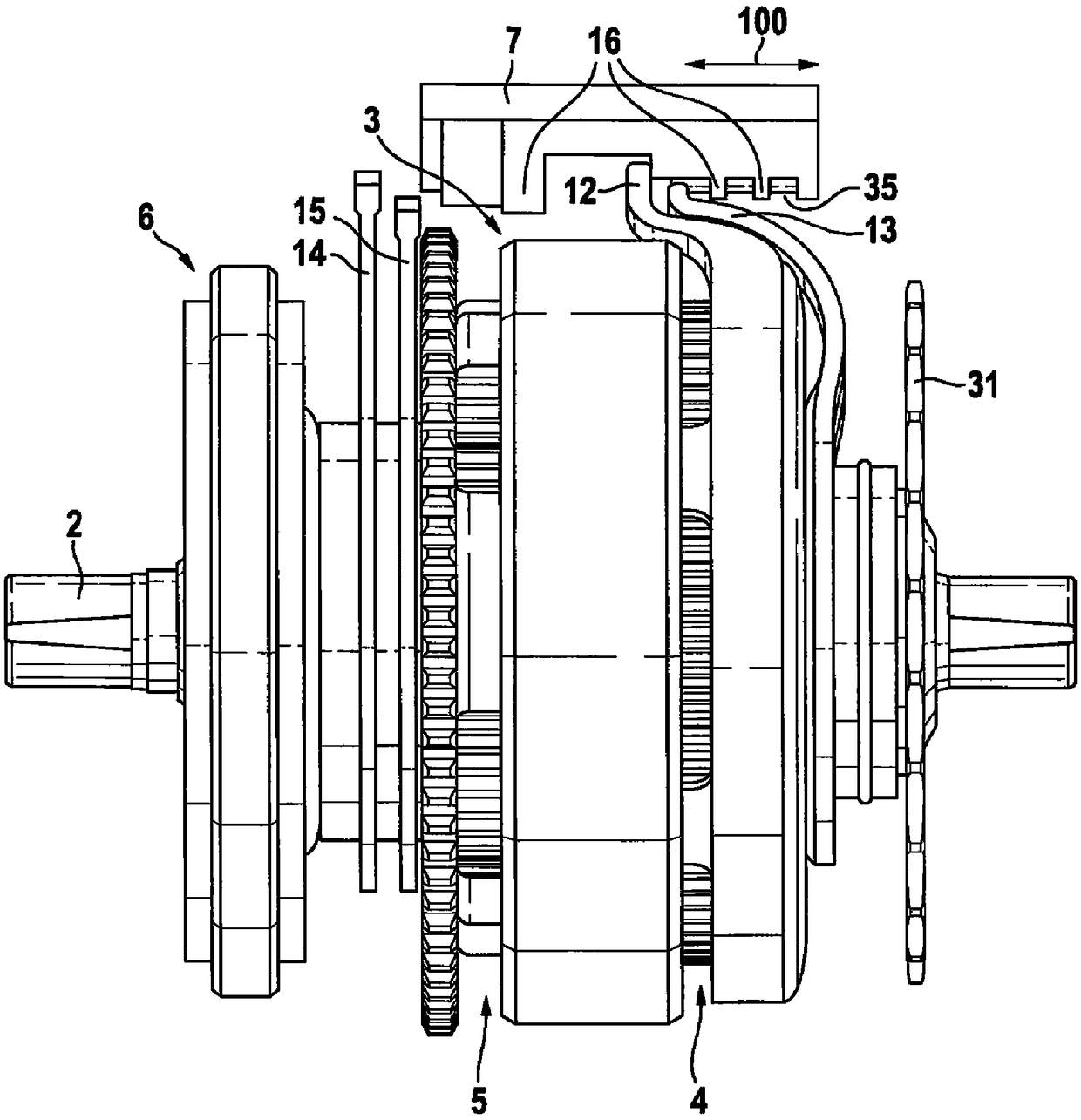
[0038] figure 1 A schematic schematic diagram showing the structure of the foot bearing driving device 1 for a bicycle. figure 2 A schematic side view of the foot bearing drive device 1 is shown. The pedal bearing drive device 1 has an integrated, load-shiftable 7-speed transmission assembly 3.

[0039] The pedal bearing drive device 1 has a pedal crankshaft 2 which can be driven by a rider of a bicycle equipped with the pedal bearing drive device 1. The force is transmitted from the pedal crankshaft 2 to the transmission assembly 3 via the freewheel 17 in particular. The pedal crankshaft 2 transmits torque to the first planet carrier 18 of the first planetary gear 4. The first planet carrier 18 is constructed in two stages and therefore has a first stage 22 and a second stage 23. Here, the first stage 22 meshes with the first sun gear 8 and the second stage meshes with the second sun gear 9. The first sun gear 8 is connected to the first shift finger 12 via a free wheel 17, ...


PUM


Abstract

The present invention relates to a bicycle bearing driving device for a bicycle comprising a pedal crankshaft for operation by a rider; a transmission assembly disposed on the pedal crankshaft and including a plurality of planetary transmissions connected to each other; The shifting slide plate is arranged in a torque-proof manner of the pedal crankshaft, and the shifting slide plate is movable along the axial direction of the pedal crankshaft, wherein the sun gear of the planetary transmission has a shifting finger respectively, and the shifting finger refers to the pedal The crankshaft extends radially outward, wherein the shifting slide has a blocking element, wherein the blocking element overlaps with the at least one shift finger in the radial direction of the pedal crankshaft, so that the shifting is made by shifting the shifting slide The overlap of the finger and the latching element in the axial and radial directions of the pedal crank prevents the single or multiple shift fingers from rotating about the pedal crank.

Description

Technical field [0001] The invention relates to a bicycle pedal bearing drive device. In particular, the bicycle has an electric motor as an auxiliary drive and is therefore an electric scooter (pedelec) or electric bicycle (Ebike). In the scope of the description of the present invention, the two words including and having the above two words are used as synonyms. Background technique [0002] An electric bicycle is known from the prior art, that is to say an electric scooter or electric bicycle. The electric bicycle has a central motor and a bicycle shifting device for matching the limited driving force of the rider to different driving resistances. . In an electric bicycle with a pedal bearing drive device, usually a chain shift device or a hub shift device is installed on the rear wheel, and the electric drive device is arranged on the pedal bearing. [0003] From the publications DE 10 2012 109 637 A1 and DE 10 2014 000 898 A1, a pedal bearing drive device with an integrate...

Claims


Application Information

Patent Timeline
Patent Type & Authority Applications(China)
IPC IPC(8): B62M11/14B62M6/55
CPCB62M6/55B62M11/14B62M3/003B62M11/145B62M11/18
Inventor M·欣特考森P·基米希
Owner ROBERT BOSCH GMBH
Features
  • R&D
  • Intellectual Property
  • Life Sciences
  • Materials
  • Tech Scout
  • Unparalleled Data Quality
  • Higher Quality Content
  • 60% Fewer Hallucinations
Learn More