A Die Kernel Structure to Reduce the Impulse of the Die Cavity

A cavity and punch technology, applied in the field of automobile base die-casting molds, can solve the problems of damage to the position of the cavity close to the runner opening, difficulty in accurately controlling the stroke of the needle, and reducing the service life of the cavity, so as to reduce the amount of punching out, The effect of reducing mold cost and improving qualification rate

Active Publication Date: 2021-06-11
NINGBO HUASHUO MOLDING & MACHINE
View PDF5 Cites 2 Cited by
  • Summary
  • Abstract
  • Description
  • Claims
  • Application Information

AI Technical Summary

Problems solved by technology

When die-casting the rib pattern 41 here, in order to ensure the molding quality of the rib pattern 41, it is necessary to place several irregular rib inserts at the bottom of the mold core. Ejection, the embossed insert will be ejected together with the product, and then the embossed insert will be separated from the product one by one, the operation is cumbersome, and the embossed rib pattern is easily damaged during the process of removing the embossed insert41
[0004] Existing molds for the production of automobile bases are generally directly connected with the runner and the mold cavity, which will cause the molten metal in the runner to directly wash the inner wall of the mold cavity, which will greatly reduce the service life of the mold cavity. severely damaged
In addition, the mold is generally provided with a slag bag directly at the end of the runner. The slag bag is used to accommodate the cold molten metal that enters first, but as the subsequent hot molten metal continues to enter, more hot molten metal will rush into the slag. The cold metal liquid in the slag bag mixed with the hot metal liquid is flushed out into the mold cavity, which reduces the quality of the product
[0005] In the mold, insert pins are generally installed at the position where the auxiliary product oblique hole is formed, and then the insert pins are driven to expand and contract by the oil cylinder, and the oil cylinders are all in a large range, so it is difficult to precisely control the stroke of the insert pins, resulting in greater waste

Method used


Image

  • A Die Kernel Structure to Reduce the Impulse of the Die Cavity
  • A Die Kernel Structure to Reduce the Impulse of the Die Cavity
  • A Die Kernel Structure to Reduce the Impulse of the Die Cavity

Examples


Embodiment Construction

[0024] Below in conjunction with specific embodiment, further illustrate the present invention. It should be understood that these examples are only used to illustrate the present invention and are not intended to limit the scope of the present invention. In addition, it should be understood that after reading the teachings of the present invention, those skilled in the art can make various changes or modifications to the present invention, and these equivalent forms also fall within the scope defined by the appended claims of the present application.

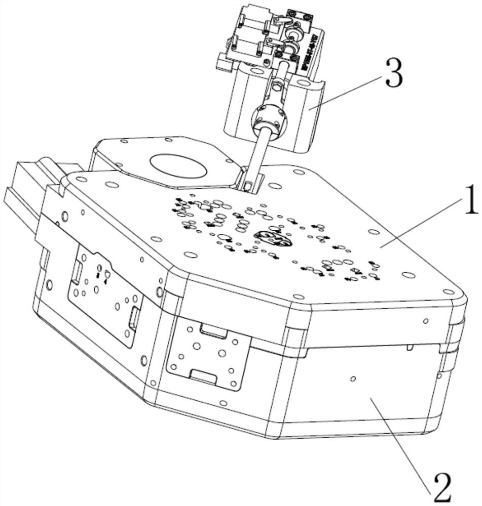
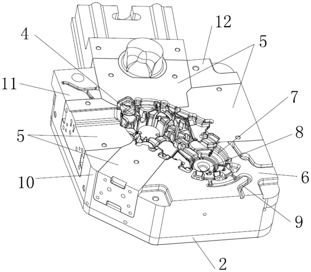
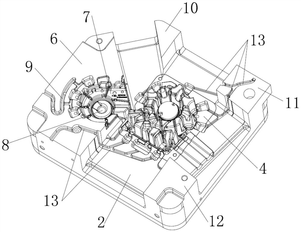
[0025] Embodiments of the present invention relate to a mold core structure that reduces the impact force of the mold cavity, such as Figure 1-8 As shown, it includes an upper mold core 1 and a lower mold core 2 installed between the upper mold frame and the lower mold frame. There is a mold cavity between the upper mold core 1 and the lower mold core 2, and the lower mold core 2. A double insert assembly 4 is provided in the...


PUM


Abstract

The invention relates to a mold core structure that reduces the impact force of the mold cavity. The lower end surface of the left feed insert and the lower end surface of the right feed insert are both auxiliary molding surfaces. The existence of the feed groove is equivalent to the feeding corner, reducing the The impact of the molten metal in the flow channel entering the mold cavity, the feed groove is also a vulnerable part, and the feed groove and auxiliary molding surface are integrated on the feed insert, which greatly reduces the cost of the mold; the curved corner of the hook groove It can effectively reduce the impulsive force of subsequent hot molten metal continuously entering the circular storage tank, thereby reducing the amount of cold metal flushing out of the circular storage. The width of the hook groove is much smaller than the width of the slag feed groove, which can also reduce the The impulsive force of molten metal; loosen the limit screw, the limit ring can slide axially along the sliding sleeve, after adjusting the limit ring to the desired position, tighten the limit screw, the position of the limit ring can be locked. The contact sensor switch cooperates with the limit ring, which can control the stroke of the cylinder piston rod and the side hole insert more accurately.

Description

technical field [0001] The invention relates to the technical field of die-casting molds for automobile bases, in particular to a mold core structure for reducing the impact force of a mold cavity. Background technique [0002] The main factor affecting the quality of the car base comes from the structure of the mold. The structure of the mold design is reasonable, which can greatly reduce the failure rate of the car base. [0003] Such as Figure 8 There is an opening 40 at the bottom of the car base, and there are irregular rib lines 41 around the opening 40. The rib lines 41 are used to strengthen the stability of the opening and the edges around the car base, and increase the deformation resistance of the car base. When die-casting the rib pattern 41 here, in order to ensure the molding quality of the rib pattern 41, it is necessary to place several irregular rib inserts at the bottom of the mold core. Ejection, the embossed insert will be ejected together with the prod...

Claims


Application Information

Patent Timeline
Patent Type & Authority Patents(China)
IPC IPC(8): B22D17/22
CPCB22D17/22
Inventor 王洪彪沈善忠旷鑫文陈发明蔡朝新黄清波徐纪波陆轶奇沈静道王鹏吕衍伟乔金超夏志忠
Owner NINGBO HUASHUO MOLDING & MACHINE
Why Eureka
Try Eureka