Integrated robot joint module

A technology of robot joints and joints, which is applied in the field of machinery, can solve problems such as single working environment, low load-to-weight ratio, robot damage, etc., and achieve the effects of simplifying the transmission structure, saving structural space, and compact internal structure

Inactive Publication Date: 2020-01-10
东莞市本润机器人科技股份有限公司
View PDF5 Cites 1 Cited by
  • Summary
  • Abstract
  • Description
  • Claims
  • Application Information

AI Technical Summary

Problems solved by technology

[0002] Although traditional robots are still active in the fields of industrial manufacturing services, the development of the times has made people's needs for production, life, entertainment, medical care and services increasingly novel. Traditional robots cannot meet these requirements in terms of structure, control and intelligence. People need more portable, more integrated, more intelligent robots, and require robots to be able to safely cooperate with people
However, robots that have been widely used in various fields generally have the following problems: (1) The hardware structure is large and heavy, and the mechanical arm is made of rigid steel and other materials, and even equipped with an arm balance mechanism to reduce nonlinear interference. Low self-weight ratio; (2) The working environment is specific and predictable, and the robot base is basically fixed to complete the task, lacking flexibility; (3) Low integration, strong joints, anti-static, dust-proof and heat dissipation Poor performance, etc., cause the robot to be easily damaged and cause losses

Method used


Image

  • Integrated robot joint module
  • Integrated robot joint module
  • Integrated robot joint module

Examples


Embodiment 1

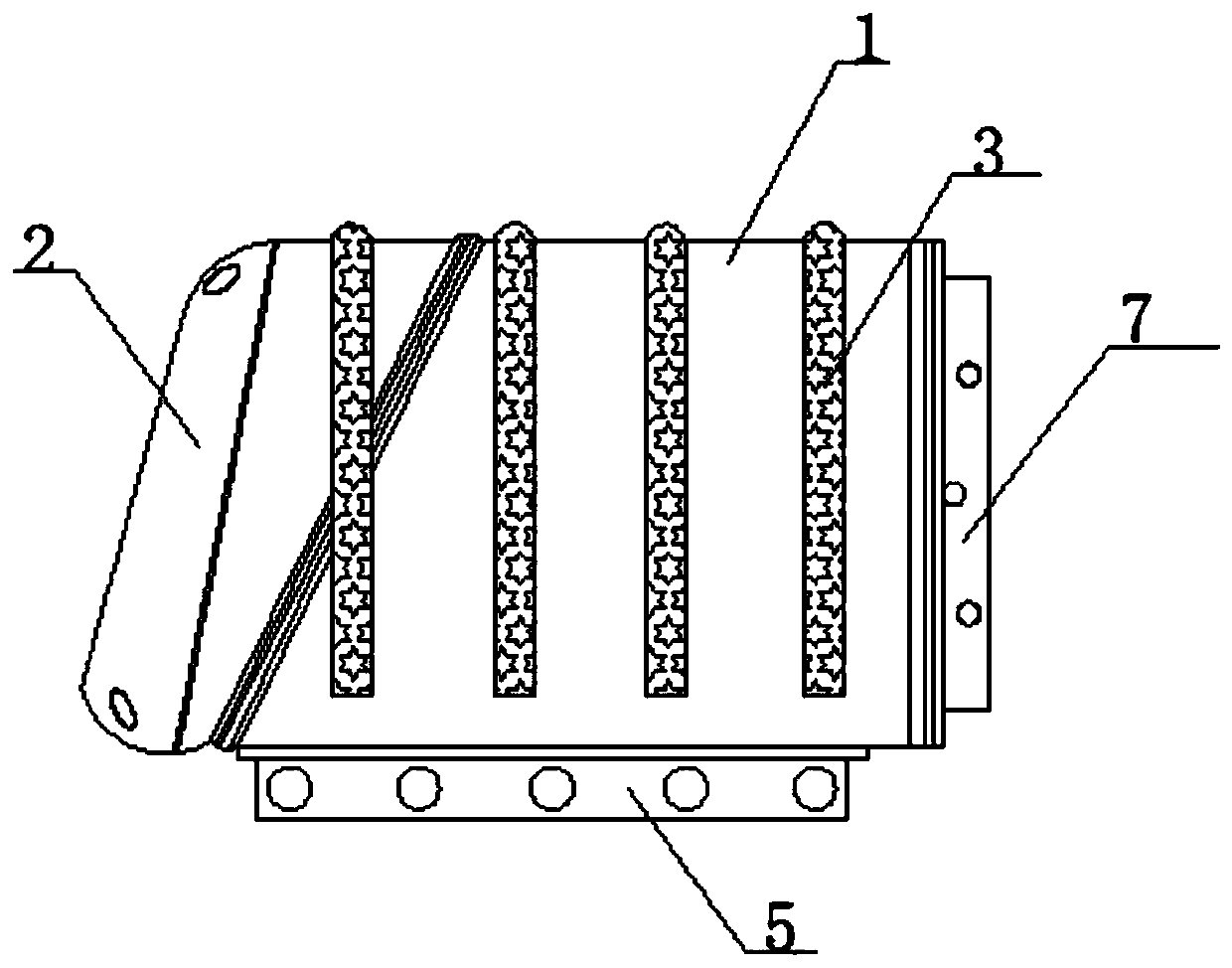
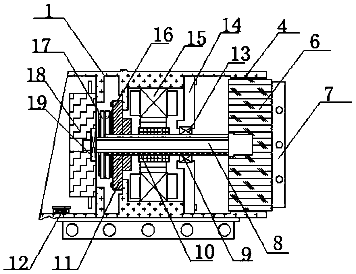
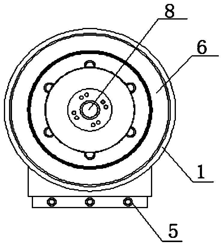
[0041] like Figure 1-5 As shown, an integrated robot joint module includes a joint housing 1 and an end cover 2. A frameless motor 15 is installed in the joint housing 1 through an annular slot, and a rotor 10 is provided in the frameless motor 15. The A low-voltage motor driver 18 is mounted on one side of the frameless motor 15 through fastening bolts, and a bearing seat 14 is installed on the other side of the frameless motor 15 through fastening bolts, and the hollow input shaft 9 is installed in the bearing seat 14 through the No. 1 bearing 13, And the hollow input shaft 9 is sleeved in the rotor 10, one end of the hollow input shaft 9 is fixedly connected to the harmonic reducer 6, and the harmonic reducer 6 is located at the end of the joint housing 1, and the harmonic reducer 6 is a The side output end is fixedly connected to the joint output disc 7, and one end of the joint output disc 7 is welded with a hollow output shaft 8, and one side of the low-voltage motor dr...

Embodiment 2

[0066] like Figure 1-5 As shown, an integrated robot joint module includes a joint housing 1 and an end cover 2. A frameless motor 15 is installed in the joint housing 1 through an annular slot, and a rotor 10 is provided in the frameless motor 15. The A low-voltage motor driver 18 is mounted on one side of the frameless motor 15 through fastening bolts, and a bearing seat 14 is installed on the other side of the frameless motor 15 through fastening bolts, and the hollow input shaft 9 is installed in the bearing seat 14 through the No. 1 bearing 13, And the hollow input shaft 9 is sleeved in the rotor 10, one end of the hollow input shaft 9 is fixedly connected to the harmonic reducer 6, and the harmonic reducer 6 is located at the end of the joint housing 1, and the harmonic reducer 6 is a The side output end is fixedly connected to the joint output disc 7, and one end of the joint output disc 7 is welded with a hollow output shaft 8, and one side of the low-voltage motor dr...


PUM


Abstract

The invention discloses an integrated robot joint module which comprises a joint shell and an end cover. A frameless motor is installed in the joint shell through an annular clamping groove, and a rotor is arranged in the frameless motor. One side of the frameless motor is provided with a low-voltage motor driver through fastening bolts. The other side of the frameless motor is provided with a bearing block through fastening bolts. A hollow input shaft is installed in the bearing block through a first bearing, and the hollow input shaft is sleeved with the rotor. One end of the hollow input shaft is fixedly connected with a harmonic reducer, and the harmonic reducer is located at the end of the joint shell. The output end of one side of the harmonic reducer is fixedly connected with a joint output disc, and a hollow output shaft is welded to one end of the joint output disc. One side of the low-voltage motor driver is provided with a second bearing through a round installation groove.According to the integrated robot joint module, the transmission structure is simplified, the internal structure is compact, installation and maintenance are more convenient, the dust-proof performance and heat dissipation performance are good, the working stability of the robot joint module is effectively guaranteed, and the service life is prolonged.

Description

technical field [0001] The invention belongs to the technical field of machinery, and in particular relates to an integrated robot joint module. Background technique [0002] Although traditional robots are still active in the fields of industrial manufacturing services, the development of the times has made people's needs for production, life, entertainment, medical care and services increasingly novel. Traditional robots cannot meet these requirements in terms of structure, control and intelligence. People need more portable, more integrated, and more intelligent robots, and require robots to be able to safely cooperate with people. However, robots that have been widely used in various fields generally have the following problems: (1) The hardware structure is large and heavy, and the mechanical arm is made of rigid steel and other materials, and even equipped with an arm balance mechanism to reduce nonlinear interference. Low self-weight ratio; (2) The working environmen...

Claims


Application Information

Patent Timeline
Patent Type & Authority Applications(China)
IPC IPC(8): B25J17/00B25J17/02B25J19/00
CPCB25J17/00B25J17/02B25J19/00B25J19/0054
Inventor 熊家鹏蒋仕龙王红星
Owner 东莞市本润机器人科技股份有限公司
Why Eureka
Try Eureka