
Bill trimming mechanism

A bill and edge trimming technology, applied in the direction of object supply, metal processing, pile separation, etc., can solve the problems of difficult automatic splitting of equipment, unstable state, not much, etc., achieve good market application value, improve edge trimming ability, Easy-to-use effects

Pending Publication Date: 2020-01-10
SHENZHEN YANXUNCHENG SCI & TECH CO LTD
View PDF0 Cites 0 Cited by
  • Summary
  • Abstract
  • Description
  • Claims
  • Application Information

AI Technical Summary

Problems solved by technology

[0002] At present, there are generally a row of pinholes on both sides of the multi-part tax stamps on the market. The purpose is for printer positioning and paper feeding design. When splitting, due to the existence of the burrs on the pinholes, it is difficult to automatically split the equipment or the splitting effect is not good; in order to reduce the impact of the pinhole burrs on the automatic splitting, one of the commonly used methods is to pass the bill The driving device conveys the bills from the printer and at the same time cuts off the pinhole edges on both sides of the bills with the conveying cutter. The cutting knife cuts off the pinhole edge of the invoice. The bill adopts the traditional way of driving the upper and lower pressure wheels to trim the edge, which will easily lead to unstable state during the movement, that is, the cutting edge is not straight or continuous; A mechanism that can stably cut off the edge of the invoice pinhole to solve the above problems

Method used


Image

  • Bill trimming mechanism
  • Bill trimming mechanism
  • Bill trimming mechanism

Examples


Embodiment 2

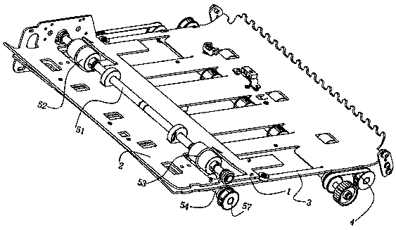
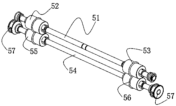
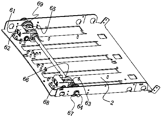
[0030] Embodiment 2, on the basis of Embodiment 1, the right cutter group 7 includes a right belt frame 71, a secondary conveying group 72, a main conveying group 2 73, a lower conveying belt 74 and a lower cutter shaft 75, the main conveying group The second 73 and the secondary conveying group 72 respectively pass through the main belt rotating shaft one and the secondary belt rotating shaft 78 to pass through the rear side and the front side of the right belt frame 71, and pass the lower conveying belt 74 from the conveying group two 72 and the main conveying group two 73 Connected, and the two ends of the lower cutter rotating shaft 75 between the secondary conveying group 72 and the main conveying group 73 are installed on the right belt frame 71 through the bearing two shafts, and the outer wall middle part of the lower cutter rotating shaft 75 is sleeved with a right Circular cutter 76, the top of right circular cutter 76 and the bottom of upper circular cutter 65 disloc...

Embodiment 3

[0031] Embodiment 3, on the basis of Embodiment 2, a square through hole 2 is also opened on the lower channel plate at a position corresponding to the conveying group 2 72, through which the lower conveying belt 74 and the lower right circular cutter 76 pass through. The second square through hole protrudes upwards; the upper conveying belt 66 and the lower conveying belt 74 are in contact with each other for clamping and conveying bills, and the lower end of the upper circular cutter 65 on the right and the upper end of the right circular cutter 76 are in dislocation contact to align the bills. Carry out edge trimming operation on the right side, the upper end of the left circular cutter 65 of the upper circular cutter 65 of the left side and the upper end of the left circular cutter in the left cutter group dislocation contacts to carry out edge trimming operation to the bill left side.

Embodiment 4

[0032] Embodiment 4, on the basis of Embodiment 2, the rotating drive assembly 8 includes a motor mounting base, a driving motor 81, a driving main pulley 82, a driving slave pulley 83 and a driving belt, and the fixed end of the driving motor 81 is fixed on the motor mounting base. The top of right belt holder 71, the working end of driving motor 81 is fixedly connected with the center of driving main pulley 82, and driving main pulley 82 is connected with driving belt pulley 83 on the upper cutter rotating shaft 64 right-hand sides by the driving belt, and driving from pulling pulley 83 And upper main gear 69 are all sleeved on the same side of the outer wall of upper cutter rotating shaft 64, and driving motor 81 works to drive main pulley 82 to drive main pulley 82 to drive driven by driving belt from pulley 83 and upper main gear 69 so as to realize synchronous rotation.


PUM


Abstract

The invention relates to a bill trimming mechanism which comprises a bill conveying channel. A bill driving device is arranged on the rear side of the bill conveying channel. A bill trimming device isarranged on the front side of the bill conveying channel. The upper portion and the lower portion of the bill conveying channel are provided with an upper channel plate and a lower channel plate correspondingly. The bill trimming device comprises an upper conveying cutter part and a lower conveying cutter part. The upper conveying cutter part comprises an upper belt support, first auxiliary conveying groups, first main conveying groups, an upper cutter rotating shaft and upper circular cutters. The two first auxiliary conveying groups are installed on the left side and the right side of the upper portion of the upper channel plate. The two first main conveying groups are arranged on the left side and the right side of the upper cutter rotating shaft in a sleeving mode correspondingly. Theupper cutter rotating shaft is sleeved with the two upper circular cutters on the left side and the right side. Through the rotary contact of an upper conveying belt and a lower conveying belt, the stable conveying of bills in the bill conveying channel is kept, the two circular cutters work in cooperation on the left side and the right side in the two channel plates so that the trimming operation of needle holes in the two sides of the bills can be realized, and therefore the neat trimming and complete cutting off of the bills are ensured.

Description

technical field [0001] The invention relates to the technical field of bill cutting equipment, in particular to a bill trimming mechanism. Background technique [0002] At present, there are generally a row of pinholes on both sides of the multi-part tax stamps on the market. The purpose is for printer positioning and paper feeding design. When splitting, due to the existence of the burrs on the pinholes, it is difficult to automatically split the equipment or the splitting effect is not good; in order to reduce the impact of the pinhole burrs on the automatic splitting, one of the commonly used methods is to pass the bill The driving device conveys the bills from the printer and at the same time cuts off the pinhole edges on both sides of the bills with the conveying cutter. The cutting knife cuts off the pinhole edge of the invoice. The bill adopts the traditional way of driving the upper and lower pressure wheels to trim the edge, which will easily lead to unstable state...

Claims


Application Information

Patent Timeline
IPC IPC(8): B26D1/24B26D5/08B65H5/02
CPCB26D1/245B26D5/086B65H5/02
Inventor 李功园谢展新刘佳辉
Owner SHENZHEN YANXUNCHENG SCI & TECH CO LTD
Learn More