Supercharge Your Innovation With Domain-Expert AI Agents!

Inspection well production process with bottom

A production process and inspection well technology, which is applied in artificial islands, manufacturing tools, water conservancy projects, etc., can solve problems such as multiple molds, and achieve the effect of reducing consumption and smoothing the outer surface

Inactive Publication Date: 2021-03-02
郑州市汇通水泥预制品有限公司
View PDF1 Cites 0 Cited by
  • Summary
  • Abstract
  • Description
  • Claims
  • Application Information

AI Technical Summary

Problems solved by technology

[0004] However, in such a preparation process, due to the need to wait for the poured concrete to solidify, more molds need to be used in the production process

Method used


Image

  • Inspection well production process with bottom
  • Inspection well production process with bottom
  • Inspection well production process with bottom

Examples


Embodiment 1

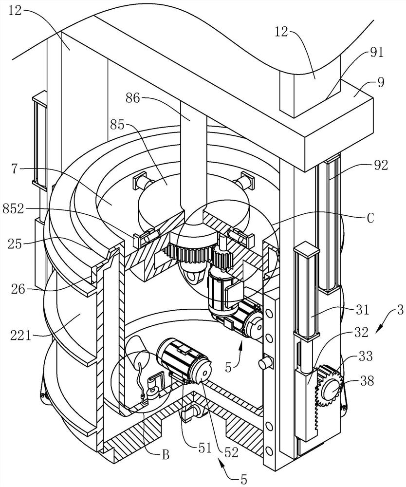
[0036] Embodiment 1: Reference figure 1 , is a kind of inspection well production equipment with a bottom disclosed by the present invention, comprising a hanger 1, a mold 2 is arranged on the lower part of the hanger 1, the mold 2 is rotatably supported on the hanger 1, and the mold 2 is mounted on the hanger 1 The rotation axis is arranged horizontally, and the overturning device 3 is fixedly arranged on the hanger 1, and the overturning device 3 is used to drive the mold 2 to rotate vertically by 180 degrees, so that the mold 2 is turned up and down.

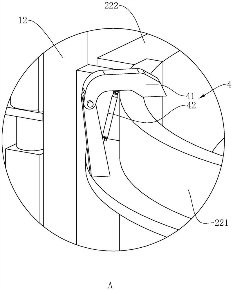
[0037] refer to figure 1 and image 3 , the mold 2 comprises an inner mold 21, an outer mold 22 and a bottom template 23, the inner mold 21 is a cylindrical barrel shape, the diameter of the inner mold 21 is less than the inner diameter of the outer mold 22, and the outer mold 22 is set outside the inner mold 21 and is connected with the inner mold. The molds 21 are arranged on the same axis, so that a pouring space 24 is f...

Embodiment 2

[0043] Embodiment 2: A production process for inspection wells with a bottom, using the production equipment for inspection wells with a bottom in Embodiment 1, including the following steps, first prepare concrete and steel cages, and collapse the prepared concrete The concrete slump is less than 10mm; the cylindrical inner mold 21 is hoisted on the ground, and the bottom of the inner mold 21 faces upwards, and then the bound steel cage is installed outside the inner mold 21, and an inspection well is installed at the same time The embedded part, the outer mold 22 is combined into a circular sleeve on the outside of the inner mold 21, so that a pouring space 24 is formed between the outer mold 22 and the inner mold 21, and the upper end of the outer mold 22 is higher than the upper end of the inner mold 21; Qualified concrete is poured into the pouring space 24. During the pouring process, the vibrating device 5 located on the side wall of the inner mold 21 is first started to...


PUM

PropertyMeasurementUnit
slumpaaaaaaaaaa

Abstract

The invention relates to a production process for an inspection well with a bottom, which includes a, preparing concrete and a reinforcement cage, b, hoisting a cylindrical inner mold, setting the bottom of the inner mold upwards, and installing the reinforcement cage in the inner mold Outside, the outer mold is placed on the inner mold and the inner mold forms a pouring space, and the upper end of the outer mold is higher than the upper end of the inner mold; c. Pour concrete into the pouring space, vibrate and compact during the pouring process, and pour the concrete to the highest Form the bottom of the inspection well on the upper surface of the bottom of the inner mold; d, cover the bottom template at the bottom of the inspection well, and the bottom template is connected to the outer mold; e, vertically align the inner mold, the outer mold, the inspection well and the bottom template Rotate 180 degrees; f, rotate the inner mold horizontally and the center of rotation coincides with the center line of the inner mold, and at the same time move the inner mold upwards and get out of the inspection well; then open the outer mold away from the two sides of the inspection well; g, put the inspection Well maintenance. The invention has the effect of directly demoulding after pouring out of the inspection well and reducing the consumption of molds.

Description

technical field [0001] The invention relates to the technical field of inspection well production technology, in particular to a bottom inspection well production technology. Background technique [0002] The inspection well is an important part of the underground pipeline, which plays an important role in the function, maintenance, environmental protection and quality of life of urban residents of the entire underground pipeline. It can be used in pipeline systems such as drainage, sewage, tap water, gas, heat, electricity, and telecommunications, and is widely used. Due to the large-scale production in the factory, the prefabricated concrete inspection well is easy to control the product quality, the on-site installation time is short, and it is not affected by the weather and construction conditions on site. The concrete and the overall inspection well have high compressive strength and good durability. [0003] The patent document with the authorized announcement number...

Claims


Application Information

Patent Timeline
Patent Type & Authority Patents(China)
IPC IPC(8): B28B23/02E02D29/12
CPCB28B23/02E02D29/12
Inventor 王凌欣孟全力闫富杰
Owner 郑州市汇通水泥预制品有限公司
Features
  • R&D
  • Intellectual Property
  • Life Sciences
  • Materials
  • Tech Scout
  • Unparalleled Data Quality
  • Higher Quality Content
  • 60% Fewer Hallucinations
Learn More