Automatic receiving device for cnc processing

An automatic material receiving and clamping technology, applied in the field of mechanical processing, can solve the problems of high labor cost, low efficiency, and easy work fatigue of personnel, and achieve the effect of saving manpower and improving production efficiency

Active Publication Date: 2021-12-07
江苏金科森电子科技有限公司
View PDF0 Cites 0 Cited by
  • Summary
  • Abstract
  • Description
  • Claims
  • Application Information

AI Technical Summary

Problems solved by technology

[0002] At present, CNC machine tools generally use manual loading and unloading, and product separation is also manual work. The labor intensity of workers is high, resulting in high labor costs, easy work fatigue and low efficiency.

Method used


Image

  • Automatic receiving device for cnc processing
  • Automatic receiving device for cnc processing
  • Automatic receiving device for cnc processing

Examples


Embodiment 1

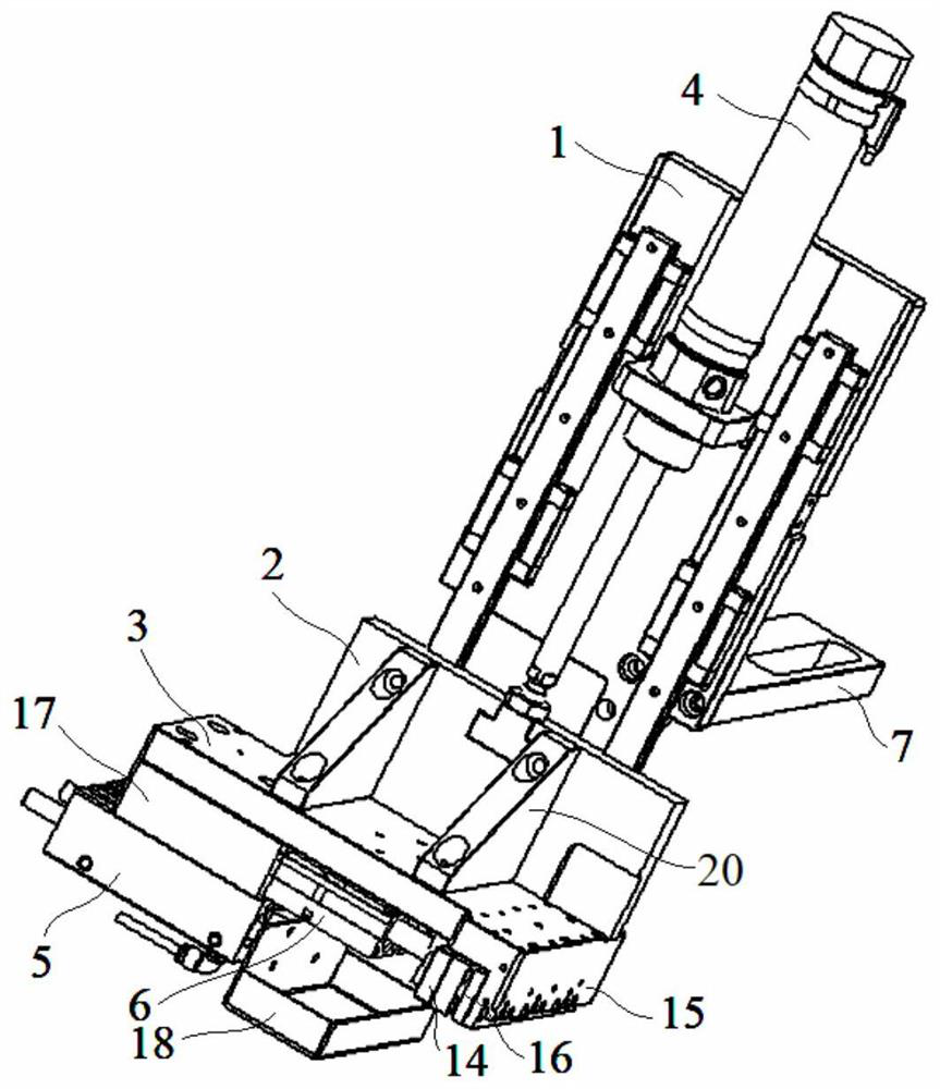
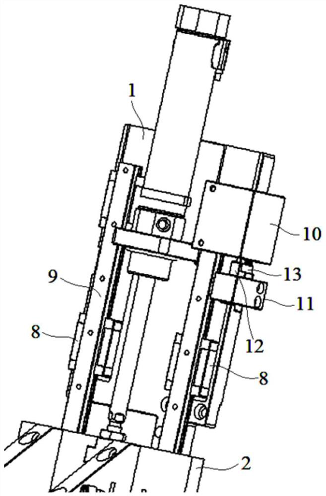
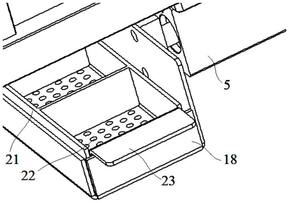
[0031] Embodiment 1: An automatic material receiving device for CNC processing, including a mounting plate 1, a movable plate 2, a base plate 3, a drive cylinder 4, a material receiving cylinder 5 and a clamping cylinder 6, and the movable plate 2 is movably installed on The front side of the mounting plate 1, the base plate 3 is fixedly installed on the lower surface of the movable plate 2, the driving cylinder 4 is installed on the mounting plate 1 and is located above the movable plate 2, the piston rod of the driving cylinder 4 is connected to the upper surface of the movable plate 2 Installed and connected, the receiving cylinder 5 and the clamping cylinder 6 are both arranged on the lower surface of the substrate 3;

[0032] The clamping cylinder 6 is installed on the lower surface of the base plate 3, the piston rod of the clamping cylinder 6 is connected with a splint 14, and the side of the base plate 3 close to the splint 14 has a downward bending portion 15, the bend...

Embodiment 2

[0037] Embodiment 2: An automatic material receiving device for CNC processing, including a mounting plate 1, a movable plate 2, a base plate 3, a drive cylinder 4, a material receiving cylinder 5 and a clamping cylinder 6, and the movable plate 2 is movably installed on The front side of the mounting plate 1, the base plate 3 is fixedly installed on the lower surface of the movable plate 2, the driving cylinder 4 is installed on the mounting plate 1 and is located above the movable plate 2, the piston rod of the driving cylinder 4 is connected to the upper surface of the movable plate 2 Installed and connected, the receiving cylinder 5 and the clamping cylinder 6 are both arranged on the lower surface of the substrate 3;

[0038]The clamping cylinder 6 is installed on the lower surface of the base plate 3, the piston rod of the clamping cylinder 6 is connected with a splint 14, and the side of the base plate 3 close to the splint 14 has a downward bending portion 15, the bendi...


PUM


Abstract

The invention discloses an automatic material receiving device for CNC processing, which includes a mounting plate, a movable plate, a base plate, a driving cylinder, a material receiving cylinder and a clamping cylinder, the movable plate is movably installed on the front side of the mounting plate, and the base plate is fixed Installed on the lower surface of the movable plate, the driving cylinder is installed on the mounting plate and located above the movable plate, the piston rod of the driving cylinder is connected to the upper surface of the movable plate, and a side surface of the mounting plate close to the limit block is installed A stopper, a handle is provided on one side of the pick-and-place box, a T-shaped block is connected to the end of the piston rod of the drive cylinder, and a T-shaped slot for the T-shaped block to be embedded is opened on the upper surface of the movable plate. The lower surface of the plate is provided with an air groove connected with the air inlet, and the base plate located below the air groove is provided with a plurality of air outlet holes connected with the air groove. The invention realizes the floating connection between the piston rod of the cylinder and the movable block, has a certain tolerance, and prevents situations such as being stuck during the up and down movement of the movable block.

Description

technical field [0001] The invention relates to an automatic material receiving device for CNC processing, and relates to the technical field of mechanical processing. Background technique [0002] At present, CNC machine tools generally use manual loading and unloading, and product separation is also manual work. The labor intensity of workers is high, resulting in high labor costs, easy work fatigue and low efficiency. Contents of the invention [0003] The object of the present invention is to provide an automatic material receiving device for CNC machining, which realizes the floating connection between the cylinder piston rod and the movable block, has a certain tolerance, and prevents the movable block from Stuck and other situations occur during the up and down movement. [0004] In order to achieve the above object, the technical solution adopted in the present invention is: an automatic material receiving device for CNC machining, including a mounting plate, a mo...

Claims


Application Information

Patent Timeline
Patent Type & Authority Patents(China)
IPC IPC(8): B65G47/74
CPCB65G47/74
Inventor 徐金根张金山
Owner 江苏金科森电子科技有限公司
Why Eureka
Try Eureka