Flue gas desulfurization gypsum drying and calcining equipment

A desulfurized gypsum and calcination technology, which is applied in the field of desulfurized gypsum drying and calcination equipment, can solve the problems of low drying efficiency, lower temperature of desulfurized gypsum, and inability to quickly dry desulfurized gypsum, and achieve the effect of increasing drying efficiency and improving efficiency

Inactive Publication Date: 2020-01-10
邵阳金拓科技开发有限公司
View PDF4 Cites 1 Cited by
  • Summary
  • Abstract
  • Description
  • Claims
  • Application Information

AI Technical Summary

Problems solved by technology

[0003] In the prior art, the drying equipment and calcination equipment are separated, occupying space, and need to be transported one more time. At the same time, the drying device cannot quickly dry the desulfurized gypsum accumulated inside, and the drying efficiency is low. At the same time, the desulfurized gypsum is dried. Finally, it will be transported to the calcination device through the conveyor belt. The dried desulfurized gypsum stays outside for a long time, and the temperature of the desulfurized gypsum itself decreases.

Method used


Image

  • Flue gas desulfurization gypsum drying and calcining equipment
  • Flue gas desulfurization gypsum drying and calcining equipment
  • Flue gas desulfurization gypsum drying and calcining equipment

Examples


Embodiment Construction

[0021] The following will clearly and completely describe the technical solutions in the embodiments of the present invention with reference to the accompanying drawings in the embodiments of the present invention. Obviously, the described embodiments are only some, not all, embodiments of the present invention. Based on the embodiments of the present invention, all other embodiments obtained by persons of ordinary skill in the art without making creative efforts belong to the protection scope of the present invention.

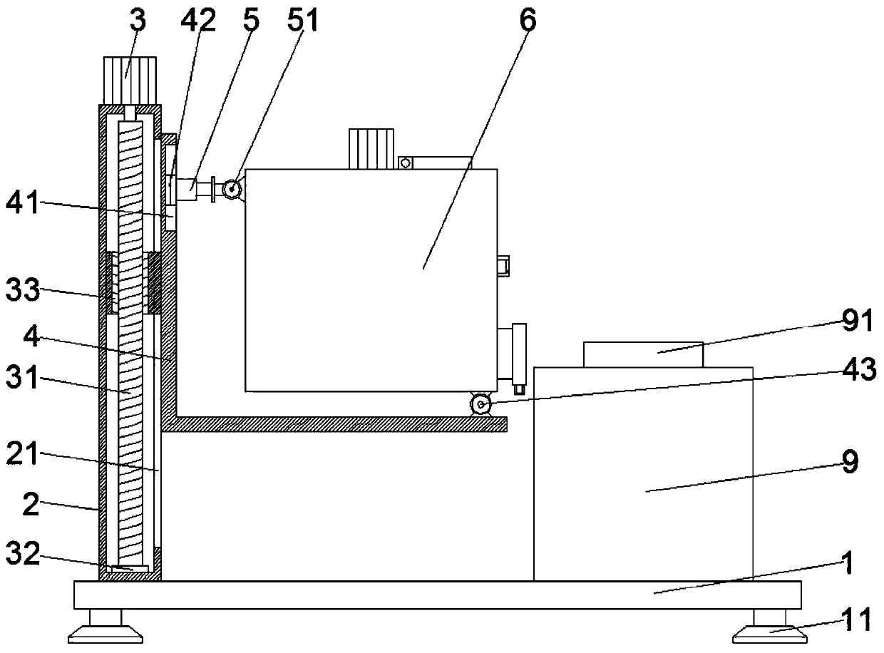
[0022] see Figure 1~3 , in an embodiment of the present invention, a desulfurization gypsum drying and calcining equipment, including a base 1 and supporting legs 11, four supporting legs 11 are symmetrically installed on the lower end of the base 1, and the four supporting legs 11 are respectively distributed under the base 1 At the four corners of the end face, a column 2 is installed on the left part of the upper end of the base 1, a sliding groove 21 is v...


PUM


Abstract

The invention discloses flue gas desulfurization gypsum drying and calcining equipment. The flue gas desulfurization gypsum drying and calcining equipment comprises a base and supporting legs. A standcolumn is installed on the left part of the upper end of the base, a sliding groove is vertically formed in the right end of the stand column, and a threaded rod is vertically installed in the standcolumn. The lower end of the threaded rod is rotatably connected into the bottom of the stand column, a first motor is installed at the upper end of the stand column, and the lower end of the first motor penetrates through the upper end of the stand column to be fixedly connected with the upper end of the threaded rod. An inner threaded block is arranged on the outer surface of the threaded rod ina sleeving mode, a L-shaped supporting plate is installed at the right end of the inner threaded block, a drying device is arranged at the upper end of the L-shaped supporting plate, a first rotatingshaft is arranged on the right part of the lower end of the drying device, a groove is vertically formed in the upper part of the right end of the L-shaped supporting plate, and a sliding block is arranged in the groove. An electric pushing rod is installed at the right end of the sliding block, and a second rotating shaft is installed at the right end of the electric pushing rod. According to the flue gas desulfurization gypsum drying and calcining equipment, flue gas desulfurization gypsum accumulated in the interior can be turned out and quickly dried, the drying efficiency is increased, meanwhile, the time that the dried flue gas desulfurization gypsum stays outside is reduced, so that the flue gas desulfurization gypsum still retains a certain temperature after entering a calcining device, and the calcining efficiency is improved.

Description

technical field [0001] The invention relates to a drying and calcining device, in particular to desulfurized gypsum drying and calcining equipment. Background technique [0002] Desulfurization gypsum is also known as exhaust gas desulfurization gypsum, sulfur gypsum or FGD gypsum. The main component is the same as natural gypsum, calcium sulfate dihydrate CaS04·2H20, with a content of ≥93%. Desulfurization gypsum is a by-product of the FGD process, a technology that uses lime-limestone to recover sulfur dioxide from coal or oil flue gas. This technology is to grind lime-limestone into slurry, and make the flue gas containing SO2 after dedusting pass through the slurry scrubber to remove SO2. [0003] In the prior art, the drying equipment and calcination equipment are separated, occupying space, and need to be transported one more time. At the same time, the drying device cannot quickly dry the desulfurized gypsum accumulated inside, and the drying efficiency is low. At th...

Claims


Application Information

Patent Timeline
Patent Type & Authority Applications(China)
IPC IPC(8): C04B11/036
CPCC04B11/036
Inventor 朱路遥
Owner 邵阳金拓科技开发有限公司
Why Eureka
Try Eureka