Method for solving continuous beam support counterforce

A support reaction force and support technology, applied in the field of structural mechanics, can solve the problems of complicated calculation, difficult realization, errors and so on

Inactive Publication Date: 2020-01-10
王开明
View PDF0 Cites 0 Cited by
  • Summary
  • Abstract
  • Description
  • Claims
  • Application Information

AI Technical Summary

Problems solved by technology

The shortcomings of existing methods for solving the reaction force of continuous beam supports are: the cal

Method used


Image

  • Method for solving continuous beam support counterforce
  • Method for solving continuous beam support counterforce
  • Method for solving continuous beam support counterforce

Examples


Embodiment 1

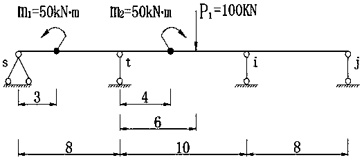
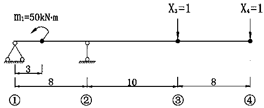
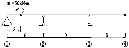
[0272] refer to Figure 1 to Figure 8 , the span combination of the continuous beam is 8+10+8 meters, and the supports s, t, i, j act on the first span with counterclockwise rotational force couple load m 1 =50KNm, the action point is x=3m from the s support, and there is a clockwise rotating dynamic couple load m on the second span 2 =50KNm, the point of action is x=4m from the support t, and the second span has the action of vertical concentrated load P 1 =100KN, x=6m from the point of action to the support t, see attached figure 1 (Schematic diagram of load action on a three-span continuous beam), find the support reaction force of the continuous beam.

[0273] Using the matrix lever method, the first span and the second span have loads, and the calculations are carried out according to the load-acting cross-column leverage method equation and the block matrix, and then the calculation results are superimposed to obtain the support reaction force. The method steps are as ...

Embodiment 2

[0390] refer to Figure 9 to Figure 12 , the continuous beam span combination is 10+10+10 meters, and the supports s, t, i, j are in the second span L ti There is a vertical concentrated load P acting on the span 1 =180KNm, the action point is x=5m from the support t, and the second span is L ti Acting linear load starting point distance t support x 1 =2m, distance from end point to support x 2 = 6m, linear load concentration Q at the starting point i =10KN, linear load concentration Q at the end point j =50KN, see attached Figure 9 , find the support reaction force of the continuous beam.

[0391] The matrix leverage method is adopted, and the method steps are as follows:

[0392] (1) The supports are numbered ①~④ from left to right, there are 2 linear equations, and the unknown quantity is X 1 、X 4 ;

[0393] (2) Remove the supports of No. ① and ④ No. load spans and replace them with X 1 = 1, X 4 =1, forming the basic calculation system of the matrix leverage me...

Embodiment 3

[0444] refer to Figure 13 to Figure 21 , the portal frame span combination is 6+10+10+6 meters, a total of 4 spans, the height of the vertical bar is 6 meters, the supports s, t, i, j, k, the supports s are hinge constraints, t , i, j, k are chain rod constraints, A, B, C, D, E are rigid nodes, and there is a vertical concentrated load P at the third span 1 = 180KN action, the action point is x = 4m away from node C, see Fig. 13, solve the support reaction force of the portal frame.

[0445] The matrix leverage method is adopted, and the method steps are as follows:

[0446] (1) The support is numbered ①~⑤ from left to right, there are 3 linear equations, and the unknown quantity is X 1 、X 2 、X 5 ;

[0447] (2) Remove the supports of No. ①, ②, ⑤ spans without load and replace them with X 1 = 1, X 2 = 1, X 5 = 1, forming the basic system of the matrix leverage method, see Figure 14 ;

[0448] (3) List the leverage method equation and establish the coefficient matrix...


PUM


Abstract

The invention relates to a method for solving continuous beam support counterforce and belongs to the technical field of structural mechanics. The invention particularly relates to a method for solving the continuous beam support reaction force. The method for solving the continuous beam support counterforce provided by the invention has the advantages of accurate and reliable calculation result and simple calculation process, and the method is a matrix lever method. According to the method, a support counterforce value is calculated by uniformly compiling numbering codes for supports, establishing a matrix lever method basic system, listing linear equations, listing matrixes, selecting basic structure calculation coefficients and free items and inputting coefficient and free item calculation results into a matrix. The matrix lever method is based on lever principle moment balance and is not based on a virtual work principle and the assumption of structural virtual displacement, the calculation method is single, disorder is not prone to occur after the numbering codes are compiled on the supports in a unified mode, the calculation is mostly repeated calculation work, the programming is simple, the calculation result precision is high, the universality is high, and the computer program operation is easy to achieve.

Description

technical field [0001] The invention belongs to the technical field of structural mechanics, specifically a method for solving the reaction force of a continuous beam support. Background technique [0002] In engineering practice, it is often encountered to check the strength and stiffness of continuous beams, which requires the calculation of the support reaction force of continuous beams, and the usual calculation methods are very complicated. The existing main methods are displacement method and force method. When the continuous beam is subjected to uniform load and linear load, these methods have surface integral or surface area graph multiplication. It is very troublesome to calculate the free terms of displacement method and force method equation. There is also the problem of certain cumulative errors in the calculation; the moment distribution method and the non-shear distribution method are asymptotic methods, which are not used by mainstream software for structural ...

Claims


Application Information

Patent Timeline
IPC IPC(8): G01M5/00
CPCG01M5/0058
Inventor 王开明
Owner 王开明
Why Eureka
Try Eureka