Spatial-temporal resource-waveform selection management method for multi-beam centralized MIMO radar

A resource management and centralized technology, which is applied in the field of multi-beam centralized MIMO radar space-time resource-waveform selection management, can solve the problems of not comprehensively considering space-time resource allocation and waveform selection, and not considering the reasonable allocation of system resources and tracking accuracy.

Active Publication Date: 2020-01-10
UNIV OF ELECTRONICS SCI & TECH OF CHINA
View PDF14 Cites 6 Cited by
  • Summary
  • Abstract
  • Description
  • Claims
  • Application Information

AI Technical Summary

Problems solved by technology

In addition, the existing multi-beam centralized MIMO radar resource management method for multi-target tracking does not comprehensively consider space-time resource allocation and waveform selection, and does not consider the reasonable allocation of system resources while improving tracking accuracy.

Method used


Image

  • Spatial-temporal resource-waveform selection management method for multi-beam centralized MIMO radar
  • Spatial-temporal resource-waveform selection management method for multi-beam centralized MIMO radar
  • Spatial-temporal resource-waveform selection management method for multi-beam centralized MIMO radar

Examples


Embodiment Construction

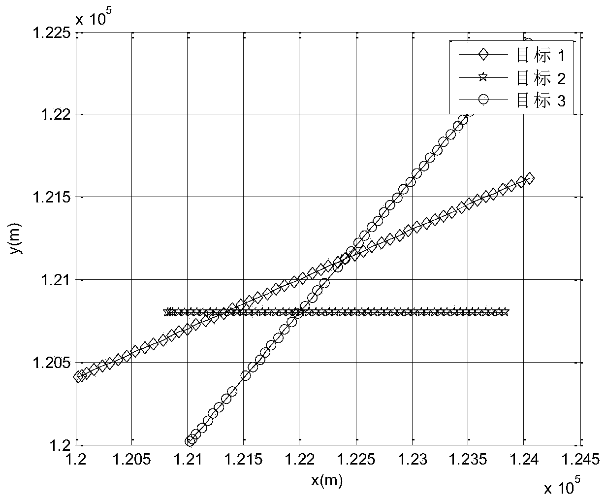
[0097] The present invention will be further described in detail below in conjunction with the accompanying drawings and embodiments. Consider the tracking of three multiple targets moving in a plane.

[0098] Assume that each sub-array transmission signal is a linear frequency modulated signal (LFM) waveform s with a Gaussian envelope k (t), as follows:

[0099]

[0100]

[0101] Among them, λ represents the duration of the waveform, and b represents the frequency modulation slope, and these two parameters can be changed adaptively. These waveforms k (t)(k=1,2,...,K) is generated by Orthogonal Frequency Division Multiplexing (OFDM), ω c is the carrier frequency, ω p is the frequency interval, and e represents the transmitted energy. For LFM, its corresponding N prei (t k , K, T, e, u, λ, b) as follows:

[0102]

[0103] c means the speed of light, SNR prei (t k , K, T, e, u) represent the signal-to-noise ratio, and the calculation is shown in formula (5); ...


PUM


Abstract

The invention belongs to the field of radar target tracking, and particularly relates to a spatial-temporal resource-waveform selection management method for a multi-beam centralized MIMO radar. The spatial-temporal resource-waveform selection management method comprehensively considers target detection and target tracking, and achieves efficient allocation of system resources in tracking processwhile improving target tracking accuracy. When solving a related algorithm, the proposed algorithm first selects combinations of a feasible sub-array division, a sampling periods, emission energy, anirradiated target set and sub-array beam pointing set parameters through a target successful irradiation limit and a target effective detection probability limit to adaptively allocate radar system resources; then further improves tracking accuracy, combines transmitted waveform parameters to form combinations of the feasible sub-array division, the sampling period, the emission energy, the irradiated target set and the sub-array beam pointing set parameters and the transmitted waveform parameters, and finally selects an optimal combination of the sub-array division, the sampling period, the irradiated target set and the sub-array beam pointing set parameters and the transmitted waveform parameters according to principle of target function minimization.

Description

technical field [0001] The invention belongs to the field of radar target tracking, and in particular relates to a multi-beam centralized MIMO radar space-time resource-waveform selection management method. Background technique [0002] MIMO (Multiple-Input Multiple-Output) radar is a new type of radar system that appeared at the beginning of the 21st century. MIMO radar is a hot spot in current research and development. According to the distance between the units of the transmitting and receiving antennas, MIMO radars can be divided into two types: distributed MIMO radars and centralized MIMO radars (see literature: P.Stoica and J.Li, "MIMO radar with colocated antennas," IEEE Signal Process. Mag., vol.24, no.5, pp.106–114, Sep.2007; A.M. Haimovich, R.S. Blum, and L.J. Cimini, “MIMO radar with widely separated antennas,” IEEE Signal Process. Mag., vol.25 , no.1, pp.116–129, Jan. 2008; J. Li and P. Stoica, MIMO Radar Signal Processing. Hoboken, NJ, USA: Wiley, 2009). [00...

Claims


Application Information

Patent Timeline
Patent Type & Authority Applications(China)
IPC IPC(8): G01S13/72G01S7/41
CPCG01S13/726G01S7/41
Inventor 程婷李茜檀倩倩
Owner UNIV OF ELECTRONICS SCI & TECH OF CHINA
Why Eureka
Try Eureka