Unmanned aerial vehicle monitoring system, base station and control method

A technology of monitoring system and control method, which is applied in the direction of traffic control system, control/regulation system, unmanned aircraft, etc., to achieve the effect of improving reliability

Active Publication Date: 2020-01-10
CORETRONIC INTELLIGENT ROBOTICS CORP
View PDF15 Cites 4 Cited by
  • Summary
  • Abstract
  • Description
  • Claims
  • Application Information

AI Technical Summary

Problems solved by technology

[0004] The present invention is aimed at a monitoring system, a base station and a control method of an unmanned aerial vehicle, and provides solutions to various problems existing in existing automatic monitoring equipment

Method used


Image

  • Unmanned aerial vehicle monitoring system, base station and control method
  • Unmanned aerial vehicle monitoring system, base station and control method
  • Unmanned aerial vehicle monitoring system, base station and control method

Examples


Embodiment Construction

[0069] The aforementioned and other technical contents, features and effects of the present invention will be clearly presented in the following detailed description of a preferred embodiment with reference to the drawings. The directional terms mentioned in the following embodiments, such as: up, down, left, right, front or back, etc., are only directions referring to the attached drawings. Accordingly, the directional terms are used to illustrate and not to limit the invention. Moreover, the term "coupled" mentioned in the following embodiments may refer to any direct or indirect connection means. Additionally, the term "signal" may refer to at least one current, voltage, charge, temperature, data, electromagnetic wave, or any other signal or signals.

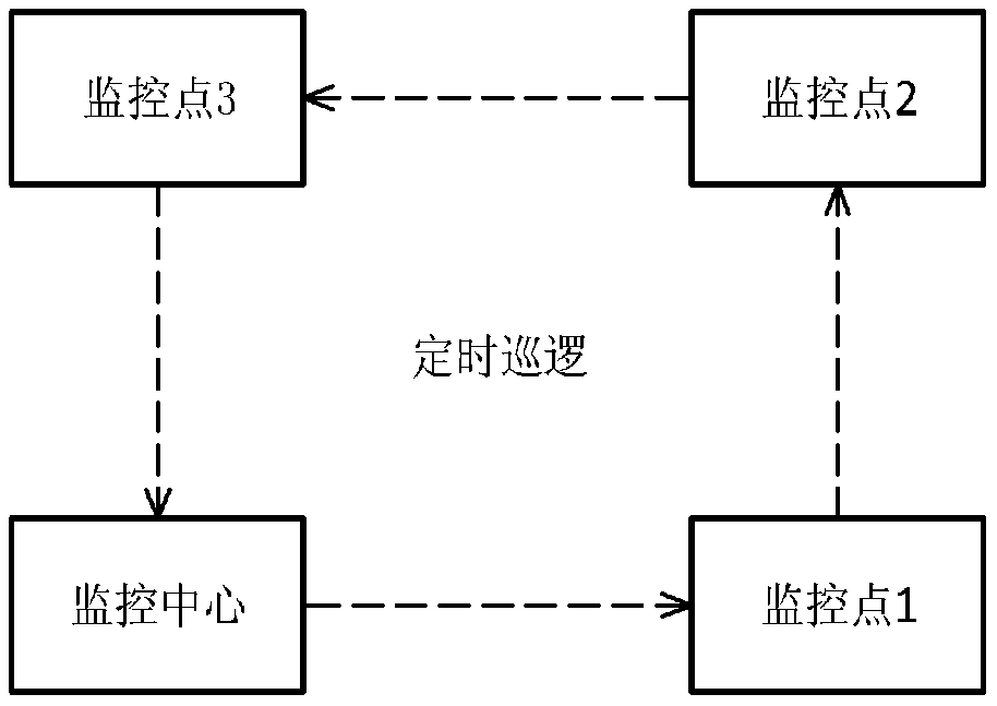
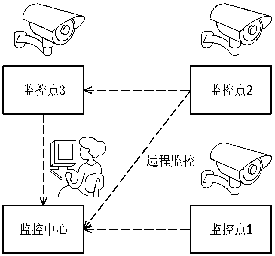
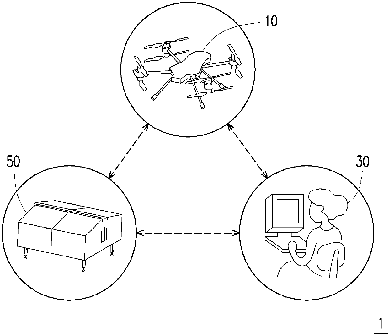
[0070] Figure 2AIt is a schematic diagram of a monitoring system 1 according to an embodiment of the present invention. Please refer to Figure 2A , the monitoring system 1 at least includes but is not limited to a drone...


PUM


Abstract

The invention provides an unmanned aerial vehicle monitoring system, a base station and a control method. The monitoring system comprises an unmanned aerial vehicle and the base station. The unmannedaerial vehicle includes a battery that supplies power to the unmanned aerial vehicle and is connected to a charging connector. The base station comprises a charging device, wherein the charging devicecomprises a power supplying connector, a power supply and a power supply controller; the power supplying connector is connected with the charging connector; the power supply provides power; and the power supply controller is coupled with the power supply and the power supplying connector, judges the battery specification of the battery, and charges the battery via the power supply according to the battery specification. Therefore, charging efficiency can be improved, and abnormal charging is avoided.

Description

technical field [0001] The invention relates to a monitoring technology, and in particular to a monitoring system, a base station and a control method of an unmanned aerial vehicle. Background technique [0002] The application of monitoring technology in all walks of life will monitor equipment, buildings, or other assets. Research units may monitor their animals or ecology, and government agencies may also monitor roads, parks, or entrances and exits. There are many kinds of existing monitoring methods. For example, see Figure 1A , for manual monitoring, security personnel are hired to patrol the monitoring point at a fixed time for site monitoring. Alternatively, please refer to Figure 1B , Fixed cameras will be set up in the monitoring field to transmit the images back to the monitoring center in real time, so as to achieve remote monitoring. Since personnel are used to monitor the field, there may be many restrictions on the convenience of monitoring and the coping...

Claims


Application Information

Patent Timeline
Patent Type & Authority Applications(China)
IPC IPC(8): G05D1/10
CPCG05D1/101B64U50/19B64U80/25B64U10/16B64U70/97B64U30/24B64U50/39B64U50/38B60L53/65B60L53/36B60L53/37B60L53/302B60L2200/10B60L2240/622B60L2260/32B64C39/04Y02T90/16Y02T10/72Y02T90/167Y02T10/70Y02T90/14Y02T10/7072Y02T90/12G05D1/0676G08G5/0013G08G5/0026G08G5/0039G08G5/0069G08G5/0091G08G5/025Y04S30/14B64U80/70B60L53/16B60L53/51B64C39/024B64U70/00
Inventor 郑旭智陈英杰谢祺栋杨易达
Owner CORETRONIC INTELLIGENT ROBOTICS CORP
Why Eureka
Try Eureka