Millimeter wave antenna and electronic equipment
A millimeter-wave antenna and millimeter-wave technology, applied in antennas, resonant antennas, electrical short antennas, etc., can solve problems such as increasing the bandwidth of millimeter-wave antennas, increasing the volume of millimeter-wave antennas, and increasing the difficulty of overall design of millimeter-wave antennas. Reduce the effect of large size and design difficulty
- Summary
- Abstract
- Description
- Claims
- Application Information
AI Technical Summary
Problems solved by technology
Method used
Image

Examples
Embodiment Construction
[0029] In order to make the purpose, technical solution and advantages of the present application clearer, the implementation manners of the present application will be further described in detail below in conjunction with the accompanying drawings.
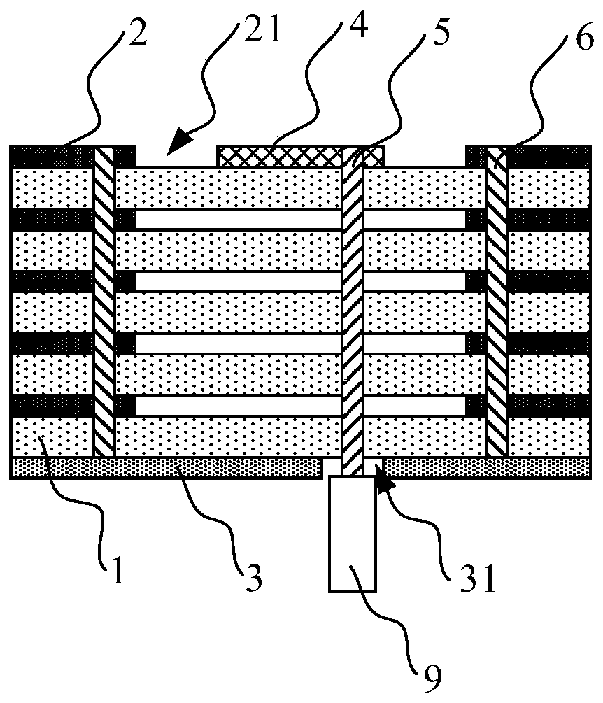
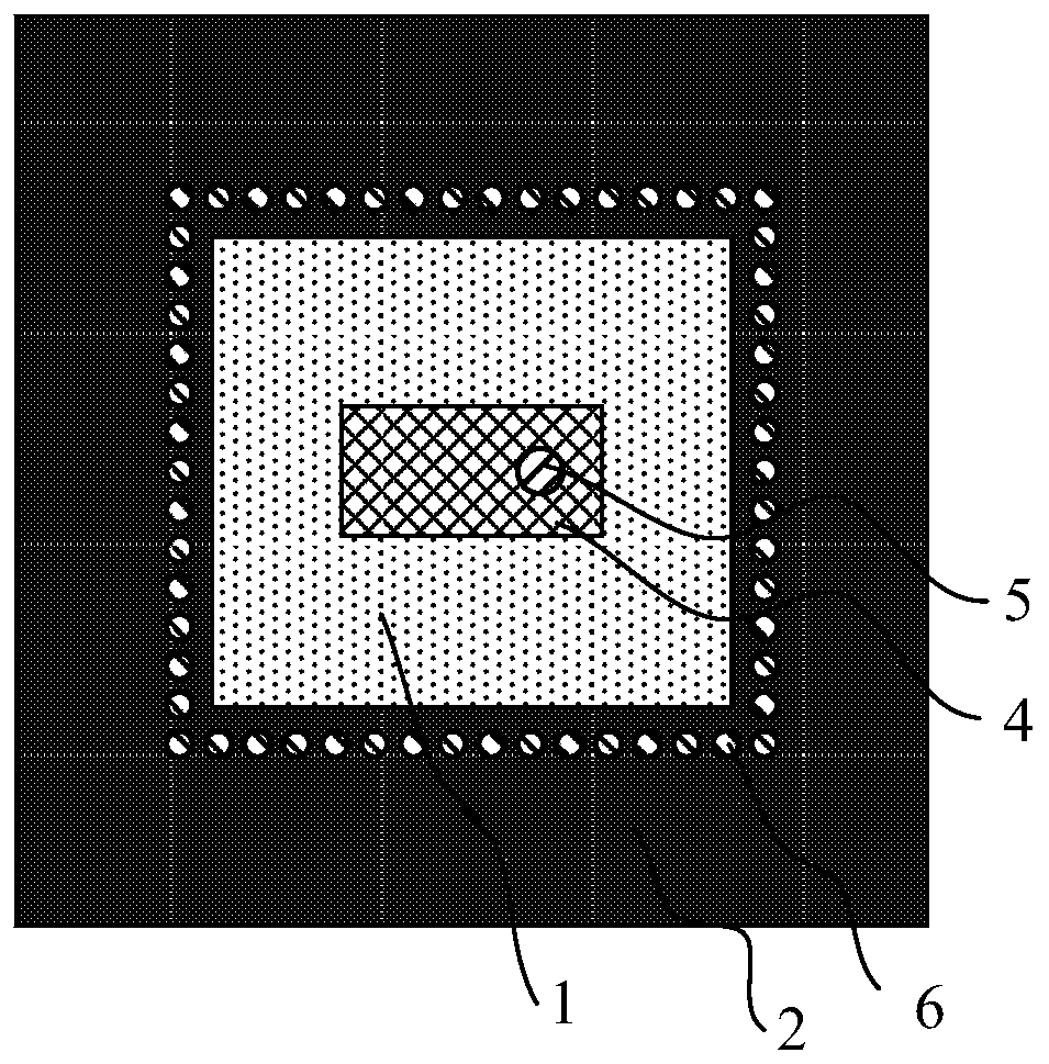
[0030] figure 1 A schematic diagram of a front view structure of a millimeter wave antenna according to an embodiment of the present application is illustrated. as attached figure 1 As shown, the millimeter wave antenna includes: an N-layer dielectric substrate 1, a first metal layer 2, a second metal layer 3, a first radiation patch 4, a feeding structure 5, and a plurality of conductive structures 6, where N is greater than or equal to 1 an integer of . The first metal layer 2, the N-layer dielectric substrate 1 and the second metal layer 3 are stacked. A plurality of conductive structures 6 pass through the N-layer dielectric substrate 1. Each conductive structure 6 is connected to the first metal layer 2 and the second meta...
PUM
 Abstract
Description
Claims
Application Information
 - Generate Ideas
- Intellectual Property
- Life Sciences
- Materials
- Tech Scout
- Unparalleled Data Quality
- Higher Quality Content
- 60% Fewer Hallucinations
Browse by: Latest US Patents, China's latest patents, Technical Efficacy Thesaurus, Application Domain, Technology Topic, Popular Technical Reports.
© 2025 PatSnap. All rights reserved.Legal|Privacy policy|Modern Slavery Act Transparency Statement|Sitemap|About US| Contact US: help@patsnap.com