Over-current protection circuit of direct-current electronic contactor

An overcurrent protection circuit and contactor technology, which is applied in emergency protection circuit devices, emergency protection devices with automatic disconnection, electronic switches, etc., can solve problems such as overcurrent damage to NMOS switch tubes, and achieve simplified high-current sampling circuits, cost reduction effect

Active Publication Date: 2020-01-10
CHANGSHA UNIVERSITY OF SCIENCE AND TECHNOLOGY
View PDF6 Cites 1 Cited by
  • Summary
  • Abstract
  • Description
  • Claims
  • Application Information

AI Technical Summary

Problems solved by technology

[0004] The invention provides an overcurrent protection circuit of a DC electronic contactor, aiming to solve the problem of overcurrent damage to the NMOS switch tube caused by the sudden change in load of the electronic contactor

Method used


Image

  • Over-current protection circuit of direct-current electronic contactor
  • Over-current protection circuit of direct-current electronic contactor
  • Over-current protection circuit of direct-current electronic contactor

Examples


Embodiment Construction

[0021] The present invention will be further explained by means of specific embodiments in combination with the accompanying drawings.

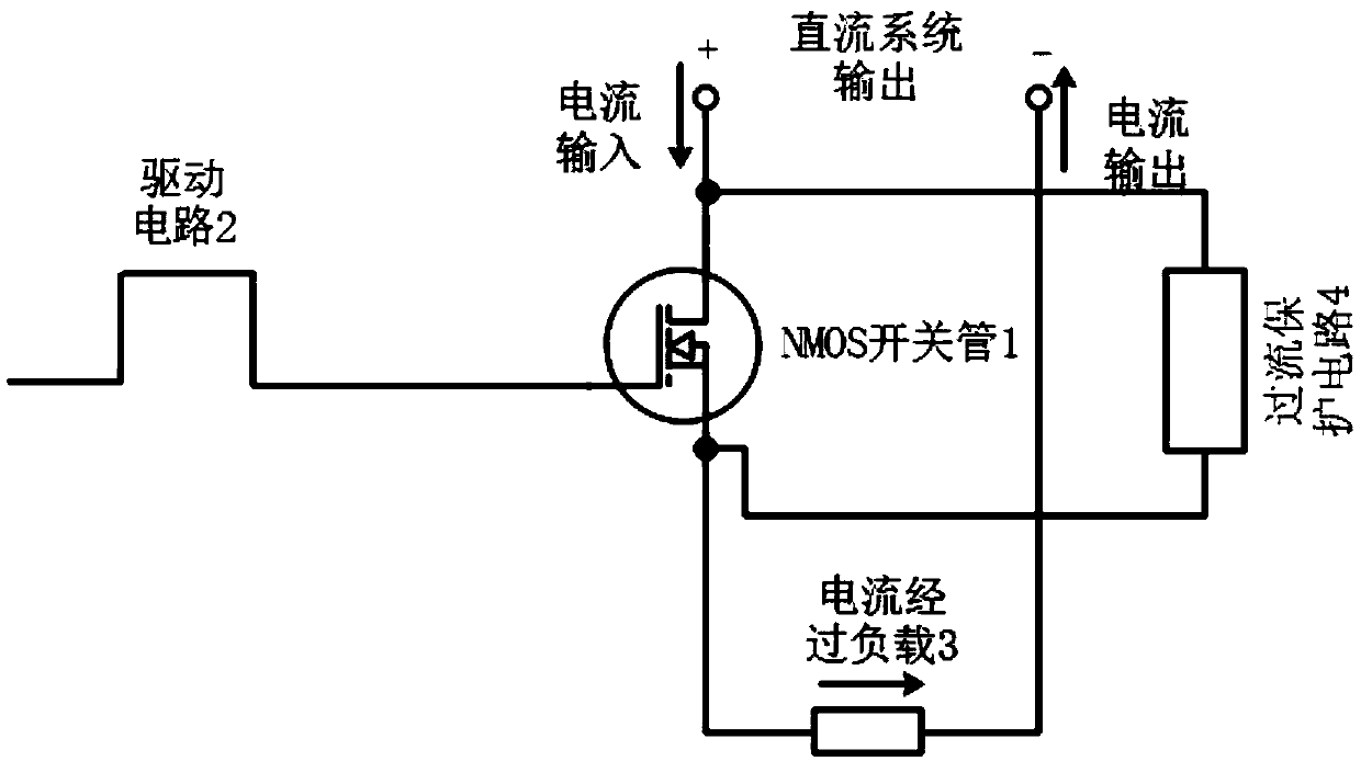
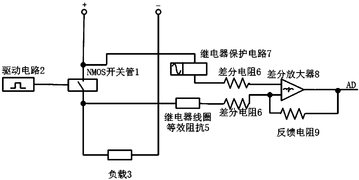
[0022] Such as figure 1 As shown, the entire circuit includes an overcurrent protection circuit 4 and a DC electronic contactor, and the DC electronic contactor includes an NMOS switch tube 1 and a driving circuit 2 . The drain (D pole) of the NMOS switch tube 1 of the DC electronic contactor is connected to the positive pole of the DC power supply, and the source (S pole) of the NMOS switch tube 1 is connected to the negative pole of the DC power supply through the load 3; NMOS switch tube 1 gate (G pole). The overcurrent protection circuit 4 includes a relay protection circuit 7, a relay coil equivalent resistance 5, a differential resistance 6, a differential amplifier 8, and a feedback resistance 9; multiple NMOS switch tubes 1 connected in the above manner are connected in parallel. The drain of the multi-channel parallel NMOS switch t...


PUM


Abstract

The invention discloses an over-current protection circuit of a direct-current electronic contactor, which is characterized in that a drain electrode of an NMOS switching transistor is connected witha positive electrode of a direct-current power supply, and a source electrode is connected with a negative electrode of the direct-current power supply through a load; and a control signal of a single-chip microcomputer is input into a grid electrode of the NMOS switching transistor through a driving circuit. Multiple paths of the NMOS switching transistor are connected in parallel. The drain electrode of the NMOS switching transistor is connected with a non-inverting input end of a differential amplifier through a relay protection circuit and a differential resistor, the source electrode ofthe NMOS switching transistor is further connected with an inverting input end of the differential amplifier through a relay coil equivalent resistor and a differential resistor, and the output end ofthe differential amplifier is connected with an AD conversion module of the single-chip microcomputer. The driving signal controls the NMOS switching transistor to be switched on. The over-current protection circuit samples voltage at the drain electrode end and the source electrode end of the NMOS switching transistor, and when the voltage exceeds a set threshold value, over-current shutdown protection is performed. The over-current protection circuit is simple in design, the use cost of the circuit can be reduced, and the reliability and the stability of the circuit during working can be improved.

Description

technical field [0001] The invention relates to the field of circuit control, in particular to an overcurrent protection circuit of a DC electronic contactor. Background technique [0002] DC power supplies are widely used in various fields of people's production and life, and common applications include electric vehicles, communications, energy, and computer room servers. In a DC power supply circuit composed of a DC power supply and a load, a mechanical contactor switch is usually used to control the on-off of the power supply circuit. However, mechanical contactors are expensive, and when used with high current, they are noisy and prone to arc damage, resulting in high cost of use. In addition, when mechanically switching, there will be pulse spike noise conduction into the surrounding power grid, polluting the grid environment. [0003] In order to solve the above problems, the patent number CN203071900U proposes an electronic contactor, but this patent does not mentio...

Claims


Application Information

Patent Timeline
Patent Type & Authority Applications(China)
IPC IPC(8): H02H3/087H03K17/08H03K17/687
CPCH02H3/087H03K17/08H03K17/687
Inventor 赵佳佳王威王伟征王新
Owner CHANGSHA UNIVERSITY OF SCIENCE AND TECHNOLOGY
Why Eureka
Try Eureka