
High-voltage and high-frequency waveform generator

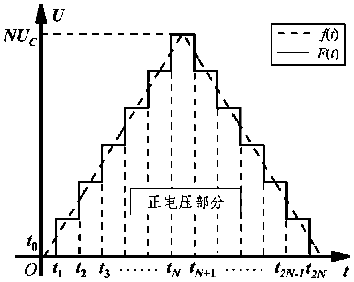
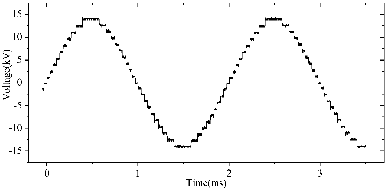
A waveform generator and step-up transformer technology, applied in the direction of output power conversion devices, electrical components, test circuits, etc., can solve the problems of low generator power, DC bias voltage, multi-power devices and auxiliary units, etc. Effects of miniaturization, fewer switching devices, and improved stability

Inactive Publication Date: 2020-01-10
XI AN JIAOTONG UNIV
View PDF7 Cites 0 Cited by
  • Summary
  • Abstract
  • Description
  • Claims
  • Application Information

AI Technical Summary

Problems solved by technology

On the one hand, the traditional method of using a signal source connected to a power amplifier to generate a high-voltage arbitrary waveform can meet a small number of applications, but the power of the generator is usually small, which restricts the application of the research on the insulation characteristics of large-capacity samples; on the other hand, the current Some use the half-bridge MMC topology to build arbitrary waveform generators. The multi-level ladder waveform output by 2n sub-modules can only reach n+1 level at most, and the output waveform will be due to the polarity effect of the test product being discharged under positive and negative voltages. Create DC Bias Problems
In addition, the high-voltage arbitrary waveform generator realized by cascading full-bridge modules requires more power devices and auxiliary units, and the overall circuit structure is complex, which is not conducive to miniaturization

Method used


Image

  • High-voltage and high-frequency waveform generator
  • High-voltage and high-frequency waveform generator
  • High-voltage and high-frequency waveform generator

Examples


Embodiment Construction

[0041] In the following description, numerous details are set forth in order to provide a more thorough illustration of embodiments of the disclosure. It will be apparent, however, to one skilled in the art that embodiments of the invention may be practiced without these specific details. In other embodiments, well-known structures and devices are shown in block diagram form, rather than in detail, in order to avoid obscuring the embodiments of the present disclosure. Furthermore, features of different embodiments described below may be combined with each other unless specifically stated otherwise.

[0042] The terms "first", "second" and the like used in the present disclosure are used to distinguish different objects, not to describe a specific order. Furthermore, "comprising" and "having", as well as any variations thereof, are intended to be inclusive and non-exclusive. For example, a process comprising a series of steps or units, or a method, or a system, or a product o...


PUM


Abstract

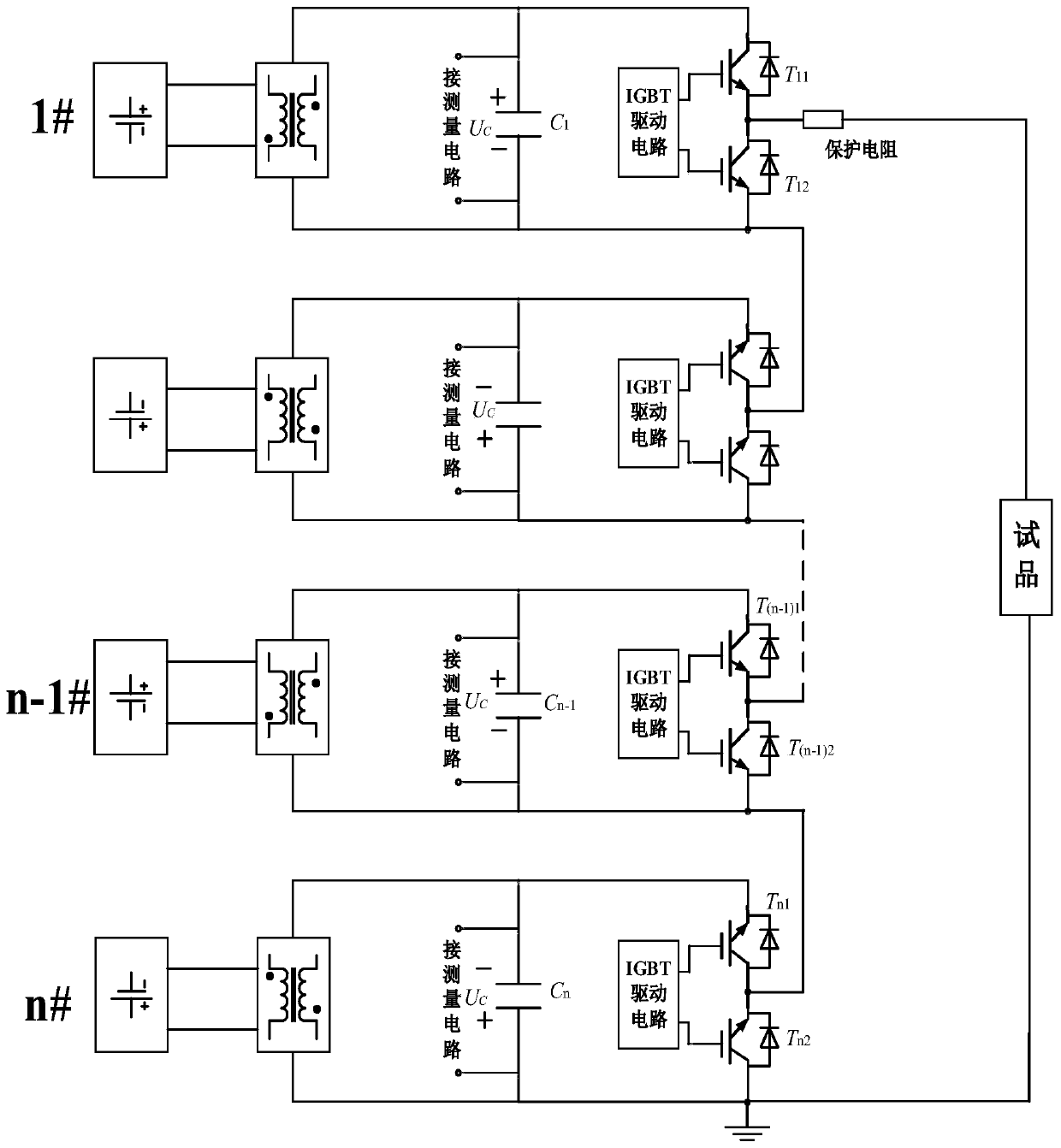
The invention discloses a high-voltage and high-frequency waveform generator which comprises multistage positive half-bridge modules and negative half-bridge modules. The positive half-bridge modulesand the negative half-bridge modules are alternately cascaded. The positive and negative half-bridge sub-modules are alternately cascaded so that the output voltage bias problem caused by asymmetric discharge in the insulation test in the traditional half-bridge MMC topology can be suppressed, the stability of the output voltage of the power supply can be improved, fewer switching device are required and miniaturization is facilitated, and expansion of series superposition to high voltage level is also facilitated.

Description

technical field [0001] The disclosure belongs to the technical field of power electronics and high-voltage power supply design, and in particular relates to a high-voltage and high-frequency waveform generator. Background technique [0002] The insulation system of high-voltage electrical equipment usually bears high-frequency step voltage waveforms, typically such as high-frequency multi-level ladder waveforms in modular multi-level converters (MMC) or DC / DC converters using MMC structures, two-voltage PWM-modulated two-level and three-level voltage waveforms output by a flat converter and a diode-clamped three-level converter. The research shows that there are obvious differences in partial discharge and insulation aging phenomena of insulating parts under two-level and multi-level pulse voltages modulated by sinusoidal voltage and PWM. The high-voltage and high-frequency waveform generator is one of the key equipment for the research on the characteristics of the insulat...

Claims


Application Information

Patent Timeline
IPC IPC(8): H02M7/539G01R31/14
CPCG01R31/14H02M7/539H02M1/0038
Inventor 庞磊李戈琦叶明天周晨晖陈炫宇张乔根赵军平刘轩东李晓昂文韬
Owner XI AN JIAOTONG UNIV
Learn More