Temperature difference generator based on micro swirl combustion

A technology of thermoelectric power generation sheet and generator, which is applied in the direction of generator/motor, burner, combustion method, etc. It can solve the problems of unstable combustion of biomass fuel, poor use experience and poor power generation effect, and achieve stable and efficient combustion.

Pending Publication Date: 2020-01-10
ZHEJIANG UNIVERSITY OF SCIENCE AND TECHNOLOGY
View PDF0 Cites 1 Cited by
  • Summary
  • Abstract
  • Description
  • Claims
  • Application Information

AI Technical Summary

Problems solved by technology

[0003] Existing thermoelectric generators usually convert heat energy into electrical energy by burning biomass, which requires frequent replenishment of biomass fuel, and the combustion of biomass fuel is not stable, and the user experience and power generation effect are poor

Method used


Image

  • Temperature difference generator based on micro swirl combustion
  • Temperature difference generator based on micro swirl combustion
  • Temperature difference generator based on micro swirl combustion

Examples


Embodiment Construction

[0044] Below in conjunction with each accompanying drawing, the present invention is described in detail.

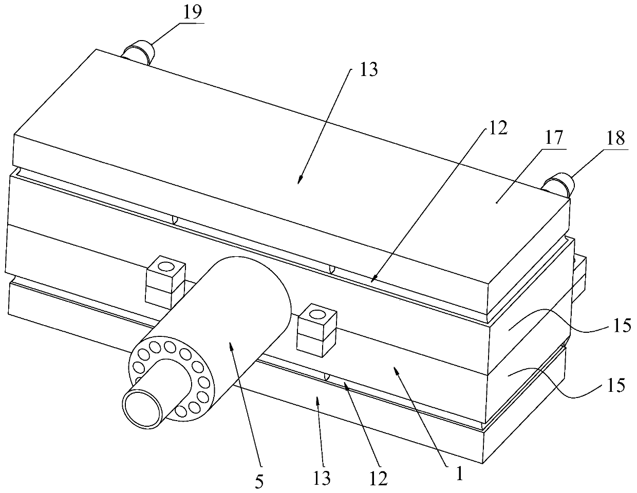
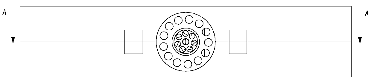
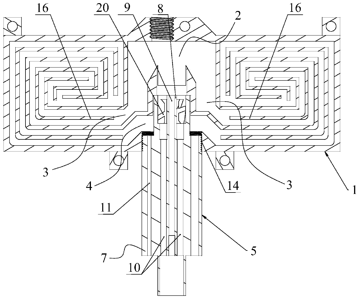
[0045] Such as figure 1 , 2 , 3, 4, 5 and 6, a thermoelectric generator based on micro-swirl combustion, including:

[0046] The heat conduction body 1, the heat conduction body 1 has a combustion chamber 2, an exhaust chamber 3 and a waste discharge chamber 4, one end of the exhaust chamber 3 communicates with the combustion chamber 2, and the other end communicates with the waste discharge chamber 4;

[0047] The air pipe 5 is installed on the heat conduction body 1, and the end part extends into the heat conduction body 1. The air pipe 5 includes a first pipe 6 and a second pipe 7 wrapped around the first pipe 6. The end of the first pipe 6 is connected to the combustion chamber 2 Connected, the middle part of the first pipe 6 has an inner pipe 8, the inner space of the inner pipe 8 is a fuel passage 9, and the end of the inner pipe 8 near the combustion chamber 2 i...


PUM


Abstract

The invention discloses a temperature difference generator based on micro swirl combustion, which comprises a heat conduction body, an air pipe, a temperature difference generation sheet, a cooling device and a controller, wherein the heat conduction body is provided with a combustion chamber, an exhaust chamber and a waste discharge chamber, one end of the exhaust chamber is communicated with thecombustion chamber and the other end is communicated with the waste discharge chamber; the air pipe is installed on the heat conduction body and comprises a first pipe and a second pipe, an inner pipe is arranged in the middle of the first pipe, a swirler is installed at the end of the inner pipe, the first pipe is further provided with a plurality of combustion-supporting air channels, the second pipe is provided with a waste discharge channel, one end of the waste discharge channel is communicated with the waste discharge cavity, and the other end is communicated with external air or an exhaust pipe; the temperature difference generation sheet abuts against the outer side wall of the heat conduction body. The swirler is arranged on the inner pipe of the temperature difference generator,so that the flow direction of combustion-supporting gas can be changed, rotational flow combustion-supporting gas is formed, and fuel can be combusted stably and efficiently.

Description

technical field [0001] The invention relates to power generation equipment, in particular to a thermoelectric generator based on micro swirl combustion. Background technique [0002] The Seebeck effect refers to the thermoelectric phenomenon in which the voltage difference between two substances is caused by the temperature difference between two different electrical conductors or semiconductors. The thermoelectric generator uses the Seebeck effect to convert heat energy into electrical energy. In order to generate electrical energy in the field and other places, a thermoelectric generator can be designed by using this characteristic of the thermoelectric generator. [0003] Existing thermoelectric generators usually convert heat energy into electrical energy by burning biomass, which requires frequent replenishment of biomass fuel, and the combustion of biomass fuel is not stable, and the user experience and power generation effect are poor. Contents of the invention [...

Claims


Application Information

Patent Timeline
Patent Type & Authority Applications(China)
IPC IPC(8): H02N11/00F23D14/24
CPCF23D14/24H02N11/002
Inventor 郑友取李国能
Owner ZHEJIANG UNIVERSITY OF SCIENCE AND TECHNOLOGY
Why Eureka
Try Eureka