Continuous-moving-type knife striking mechanism

A technology of interlocking and loosening of knives, which is applied in the direction of metal processing machinery parts, clamping, support, etc., can solve problems such as easy failures and problems, high cost of electronic components, and affecting production beats, etc.

Inactive Publication Date: 2020-01-14
刘致宇
View PDF9 Cites 2 Cited by
  • Summary
  • Abstract
  • Description
  • Claims
  • Application Information

AI Technical Summary

Problems solved by technology

[0002] In the machining center, the quick tool change action of the main shaft is mainly completed by two actions: the rotation of the main shaft (tool change) and the longitudinal movement (loosening the tool, buckling the tool). The rotation of the main shaft needs to be driven by the motor through the belt transmission pair, and the main shaft The longitudinal movement of the machine is realized by various electronic components and complex mechanical structure according to the beat of the main shaft rotation, but the cost of the electronic components used in this traditional structure is relatively high, and it is prone to failure and problems. The speed is also relatively slow, taking about 4s, which affects the production beat

Method used


Image

  • Continuous-moving-type knife striking mechanism
  • Continuous-moving-type knife striking mechanism

Examples


Embodiment Construction

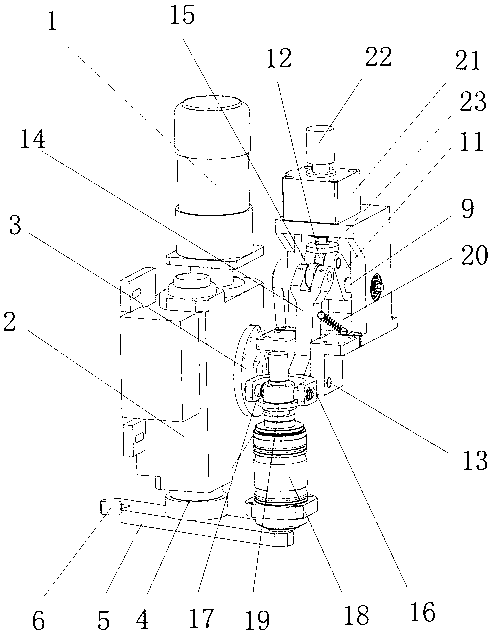
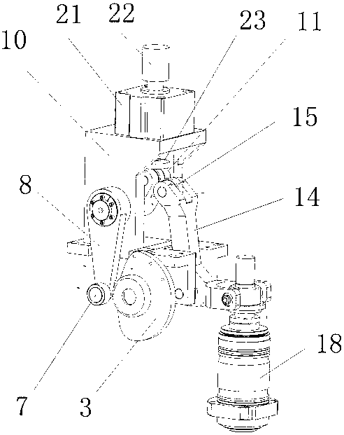
[0011] The specific implementation manner of the present invention will be described below with reference to the accompanying drawings. Such as figure 1 , figure 2 Shown: a linkage type knife-cutting mechanism, including a motor 1, the working end of the motor 1 is connected to the input end of the gearbox 2, and a cam 3 is also connected to the first output shaft of the gearbox 2, and at the same time The second output shaft of the gearbox is connected with the loose broach main shaft 4, and the bottom end of the loose broach main shaft 4 is connected with a buckle bar 5, and both ends of the buckle bar 5 are provided with claws 6,

[0012] The cam 3 is equipped with a swing arm roller 7, the swing arm roller 7 is rotatably supported on the free end of the swing arm 8, and the swing arm 8 is rotatably supported by the loose knife arm mandrel 9 and fixed on the loose knife. On the seat 10, a loose knife arm 11 is keyed on the said loose knife arm mandrel 9, and the free end...


PUM


Abstract

The invention discloses a continuous-moving-type knife striking mechanism. The continuous-moving-type knife striking mechanism is characterized in that the working end of a motor is connected to the input end of a transmission; a cam is connected to a first output shaft of the transmission; meanwhile, the second end of the transmission is connected to a knife loosening and pulling spindle; the bottom end of the knife loosening and pulling spindle is connected to a knife buckling rod; two ends of the knife buckling rod are separately provided with clamping jaw parts; a swinging arm roller is matched to the cam; the swinging arm roller is rotatably supported on the free end of a swinging arm; the swinging arm is rotatably supported on a knife loosening fixing base through a knife loosening arm mandrel; a knife loosening arm is in key joint with the knife loosening arm mandrel; the free end of the knife loosening arm is connected to a knife loosening arm roller; a spindle knife looseningarm is further rotatably supported on the bottom of the knife loosening fixing base through the spindle knife loosening arm mandrel; a spindle knife loosening arm roller is rotatably supported on thetop of the spindle knife loosening arm; and besides, the spindle knife loosening arm roller is in contact with the knife loosening arm roller.

Description

technical field [0001] The invention relates to a partial structure of a machining center, in particular to an interlocking knife-cutting mechanism. Background technique [0002] In the machining center, the quick tool change action of the main shaft is mainly completed by two actions: the rotation of the main shaft (tool change) and the longitudinal movement (loosening the tool, buckling the tool). The rotation of the main shaft needs to be driven by the motor through the belt transmission pair, and the main shaft The longitudinal movement of the machine is realized by various electronic components and complex mechanical structure according to the beat of the main shaft rotation, but the cost of the electronic components used in this traditional structure is relatively high, and it is prone to failure and problems. The speed is also relatively slow, taking about 4s, which affects the production beat. Therefore need a kind of novel synchronous knife beating mechanism that c...

Claims


Application Information

Patent Timeline
Patent Type & Authority Applications(China)
IPC IPC(8): B23Q3/155
CPCB23Q3/1552B23Q3/15503
Inventor 刘致宇
Owner 刘致宇
Why Eureka
Try Eureka