Plate-and-frame filter press with filter plate convenient to replace

A plate and frame filter press and filter plate technology, applied in the direction of filtration separation, special treatment targets, water/sludge/sewage treatment, etc., can solve the problems of large filtering force, difficult replacement, and difficult removal, etc., to achieve convenient The effect of replacement

Pending Publication Date: 2020-01-14
苏子战
View PDF0 Cites 0 Cited by
  • Summary
  • Abstract
  • Description
  • Claims
  • Application Information

AI Technical Summary

Problems solved by technology

[0002] After the sludge is concentrated and digested, it still has a water content of about 95%-97%, and its volume is still very large. Sludge dehydration can further remove the pore water and capillary water in the sludge and reduce its volume. After dehydration, the sludge The moisture content can be reduced to 70%-80%, and its volume is 1 / 10-1 / 4 of the original volume, which is conducive to subsequent transportation and treatment. The sludge mechanical dehydration methods include filtration dehydration, centrifugal dehydration and press dehydration, etc. The frame filter press is the first machine used in chemical dehydration. Although the plate and frame filter press is generally operated intermittently, the investment in infrastructure equipment is large and the filtration capacity is also low, due to its large filtering driving force and high content of filter cake The advantages of high solid rate, clear filtrate, high solid recovery rate and high conditioning drug consumption are still widely used in some small sewage plants; after the plate and frame filter press is used, due to its large pressure and sludge Solid impurities, the filter screen on the filter plate is often damaged and other problems. When replacing the filter plate of the existing plate and frame filter press, all the filter plates need to be lifted, and the filter plate to be replaced must be selected for replacement. , the filter plates are all raised, and on this basis, more manpower is often required to replace the filter plates; secondly, due to the pressure between the filter plates, when one filter plate is taken out, the other filter plates will quickly loosen, thus As a result, it is not easy to take out and more difficult to replace; therefore, there is a need for a plate and frame filter press that is easy to replace the filter plate

Method used


Image

  • Plate-and-frame filter press with filter plate convenient to replace
  • Plate-and-frame filter press with filter plate convenient to replace
  • Plate-and-frame filter press with filter plate convenient to replace

Examples


Embodiment 1

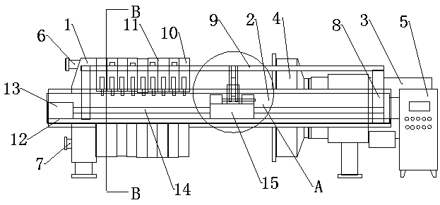
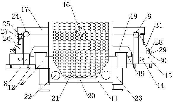
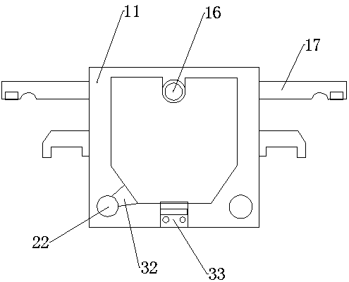
[0023] Such as Figure 1-5 As shown, a plate and frame filter press for easy replacement of filter plates includes a thrust plate 1, the front and rear of the thrust plate 1 are fixedly equipped with a main beam 2, the opposite side of the main beam 2 and An oil cylinder 3 is fixedly installed on the right end of the main beam 2, and the output end of the oil cylinder 3 is fixedly installed with a compression plate 4 that is movably connected with the two main beams 2. The front of the oil cylinder 3 is located on the right side of the main beam 2 A control box 5 is fixedly installed, and a feeding pipe 6 passing through the thrust plate 1 is fixedly installed on the left side of the thrust plate 1, and a There are two water outlet pipes 7 that run through the thrust plate 1, and the outer sides of the two main beams 2 are fixedly provided with support plates 12, and the left and right sides of the support plates 12 are provided with fixed columns 8. The top of the fixed colu...

Embodiment 2

[0026] Such as Figure 1-5 As shown, a plate and frame filter press for easy replacement of filter plates includes a thrust plate 1, the front and rear of the thrust plate 1 are fixedly equipped with a main beam 2, the opposite side of the main beam 2 and An oil cylinder 3 is fixedly installed on the right end of the main beam 2, and the output end of the oil cylinder 3 is fixedly installed with a compression plate 4 that is movably connected with the two main beams 2. The front of the oil cylinder 3 is located on the right side of the main beam 2 A control box 5 is fixedly installed, and a feeding pipe 6 passing through the thrust plate 1 is fixedly installed on the left side of the thrust plate 1, and a There are two water outlet pipes 7 that run through the thrust plate 1, and the outer sides of the two main beams 2 are fixedly provided with support plates 12, and the left and right sides of the support plates 12 are provided with fixed columns 8. The top of the fixed colu...


PUM


Abstract

The invention relates to a plate-and-frame filter press with a filter plate convenient to replace. The plate-and-frame filter press comprises a thrust plate, wherein main beams are fixedly mounted onthe front surface and the rear surface of the thrust plate; supporting plates are fixedly arranged on the outer sides of the two main beams; fixed columns are arranged on the left side and the right side of each supporting plate; fixed rods are welded to the upper portions of the fixed columns; filter frames are movably mounted on the opposite sides of the two main beams; filter plates positionedon the opposite sides of the filter frames are movably mounted on the opposite sides of the two main beams; support rods are fixedly mounted on the front surface and the rear surface of the filter plates; first motors are arranged on the left sides of the supporting plates; the output ends of the first motors are connected with screws; the screws are sleeved with sliding blocks; electric push rodsleeves are arranged above the sliding blocks; electric push rods are arranged in the electric push rod sleeves; second motors are arranged on the left sides of the upper portions of the sliding blocks; the output ends of the second motors are connected with rotating shafts; and two clamping hooks are fixedly arranged on each rotating shaft. The plate-and-frame filter press has the advantages of convenience in replacement, labor saving and low replacement difficulty.

Description

technical field [0001] The invention relates to the technical field of plate and frame filter presses, in particular to a plate and frame filter press which facilitates replacement of filter plates. Background technique [0002] After the sludge is concentrated and digested, it still has a water content of about 95%-97%, and its volume is still very large. Sludge dehydration can further remove the pore water and capillary water in the sludge and reduce its volume. After dehydration, the sludge The moisture content can be reduced to 70%-80%, and its volume is 1 / 10-1 / 4 of the original volume, which is conducive to subsequent transportation and treatment. The sludge mechanical dehydration methods include filtration dehydration, centrifugal dehydration and press dehydration, etc. The frame filter press is the first machine used in chemical dehydration. Although the plate and frame filter press is generally operated intermittently, the investment in infrastructure equipment is la...

Claims


Application Information

Patent Timeline
Patent Type & Authority Applications(China)
IPC IPC(8): C02F11/122B01D25/21B01D37/04
CPCB01D25/003B01D25/21C02F11/122C02F2303/14
Inventor 苏子战
Owner 苏子战
Why Eureka
Try Eureka