A jet pump for automatic uniform gas supply and corrosion reduction

A jet pump and uniform technology, applied in the field of jet pump, can solve the problems of hydraulic asymmetry of the throat, low feasibility, limited cavitation damage, avoid noise and severe vibration, ensure safe and stable operation, and promote high The effect of using value

Active Publication Date: 2021-01-05
SICHUAN UNIV
View PDF2 Cites 0 Cited by
  • Summary
  • Abstract
  • Description
  • Claims
  • Application Information

AI Technical Summary

Problems solved by technology

However, there are certain problems in each of the appeal measures: increasing the submersion depth of the jet pump will increase the difficulty and cost of construction; increasing the area ratio of the jet pump or reducing the working pressure of the jet pump will cause the jet pump to deviate from the optimal working condition and efficiency. Reduction: The improvement of the inlet structure of the jet pump has a limited effect on reducing the hazards of cavitation; the operation of supplementing pressure water is more complicated than supplementing air, and its feasibility is relatively low
In the prior art, when supplying air to the low-pressure area in the throat of the jet pump, a single-side air supply structure is generally adopted (such as a utility model patent for a liquid jet pump that reduces vibration and noise, application number 200720084915.0; and an invention patent for a An automatic air supply device for reducing cavitation vibration and noise of jet pumps, application number 200710052818.8), when supplying air, the asymmetric air entering the throat will cause the fluid in the throat to deviate from the main axis direction, resulting in hydraulic asymmetry in the throat problem, which in turn affects the efficiency of the jet pump

Method used


Image

  • A jet pump for automatic uniform gas supply and corrosion reduction
  • A jet pump for automatic uniform gas supply and corrosion reduction
  • A jet pump for automatic uniform gas supply and corrosion reduction

Examples


Embodiment Construction

[0024] The technical solution of the present invention will be further described in detail below in conjunction with the accompanying drawings, but the protection scope of the present invention is not limited to the following description.

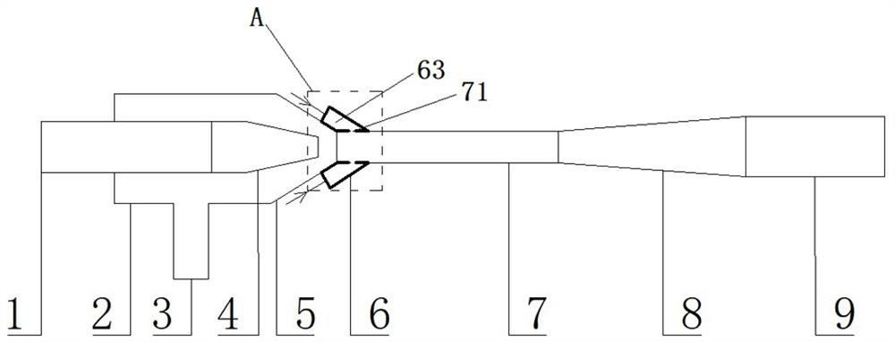
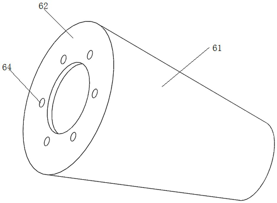
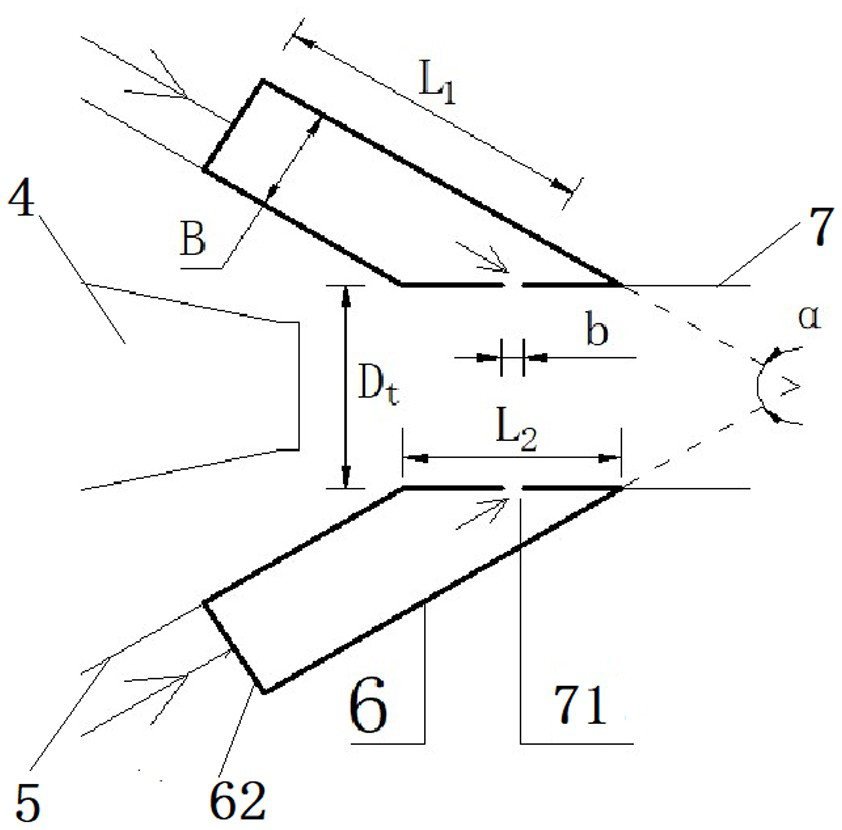
[0025] Such as figure 1 As shown, the jet pump in the prior art includes a water suction pipe 3 connected in sequence, a suction chamber 2, a throat inlet section 5, a throat pipe 7, a diffuser pipe 8 and a water outlet pipe 9, and a working water pipe 1 is inserted into the suction chamber 2 , one end of the working water pipe 1 is connected with a nozzle 4, and the nozzle 4 is arranged in the inlet section 5 of the throat pipe and facing the throat pipe 7. Such as Figure 1 to Figure 6 As shown, the present invention is a jet pump for automatically and uniformly supplying air and reducing corrosion, which adds a circumferential air equalizing groove 6 on the basis of the existing jet pump.

[0026] Such as Figure 1 to Figure 3 As show...


PUM


Abstract

The invention discloses a jet pump for automatically and uniformly replenishing air and reducing corrosion, which relates to the field of jet pumps and includes a water suction pipe, a suction chamber, an inlet section of a throat pipe, a throat pipe, a diffuser pipe, a water outlet pipe, a working water pipe, a nozzle, and a ring. Circumferential air groove, the circumferential air groove includes a cone and an annular end plate, the cone and the throat are concentrically arranged and sealed on the throat, the outer conical surface of the inlet section of the throat is parallel to the inner conical surface of the conical cylinder It is installed, and a circular air uniform channel is formed, and a number of air mixing ports connected with the circular air uniform channel are evenly distributed on the throat pipe. The outer peripheral side wall of the annular end plate is sealed with the cone tube, and the inner peripheral side wall It is sealingly connected with the outer wall of the entrance section of the throat pipe, and a plurality of air inlet holes communicated with the circumferential air uniform passage are arranged on the annular end plate in a uniform manner around the circumference. The jet pump can automatically replenish air symmetrically and evenly in the throat of the jet pump, thereby reducing the damage caused by cavitation of the jet pump and improving the efficiency of the jet pump. Meanwhile, the device has a simple structure, low cost, and is convenient and quick to use.

Description

technical field [0001] The invention relates to the field of jet pumps, in particular to a jet pump for automatically and uniformly replenishing air and reducing corrosion. Background technique [0002] The jet pump is a kind of fluid conveying machinery and mixed reaction equipment that uses high-speed fluid as the working fluid and uses jet turbulent diffusion to transfer energy and mass. In the prior art, conventional jet pumps are generally formed by connecting working water pipes, suction chambers, water suction pipes, nozzles, throat pipes, diffusion sections, and water outlet pipes. When it is working, the high-pressure working fluid is ejected through the nozzle, and the pressure energy is converted into kinetic energy to make the fluid at the outlet of the nozzle in a high-speed and low-pressure state, and the high-speed and low-pressure fluid will be sucked into the jet pump by the suction fluid. Due to the different flow velocities of the working fluid and the su...

Claims


Application Information

Patent Timeline
Patent Type & Authority Patents(China)
IPC IPC(8): F04F5/10F04F5/44
CPCF04F5/10F04F5/44
Inventor 陈云良李梦秋顾蕤王波徐永党晓强
Owner SICHUAN UNIV
Why Eureka
Try Eureka