
Free-flying support device in full-span flying wing body degree of freedom flutter wind tunnel test

A technology of wind tunnel test and support device, which is applied in measurement device, aerodynamic test, machine/structural component test, etc., can solve the problems affecting the test results of flying wing flutter characteristics, aero-servo elasticity, etc., and is easy to implement. , the effect of reducing experimental error and reducing frictional resistance

Inactive Publication Date: 2021-04-20
NORTHWESTERN POLYTECHNICAL UNIV
View PDF9 Cites 0 Cited by
  • Summary
  • Abstract
  • Description
  • Claims
  • Application Information

AI Technical Summary

Problems solved by technology

However, after the active control system is adopted, it may cause aeroservoelasticity problems, which will affect the test results of the flutter characteristics of the flying wing. Therefore, it is necessary to develop a new type of free-flying support suitable for the full-span flying wing flutter wind tunnel model test. device

Method used


Image

  • Free-flying support device in full-span flying wing body degree of freedom flutter wind tunnel test
  • Free-flying support device in full-span flying wing body degree of freedom flutter wind tunnel test
  • Free-flying support device in full-span flying wing body degree of freedom flutter wind tunnel test

Examples

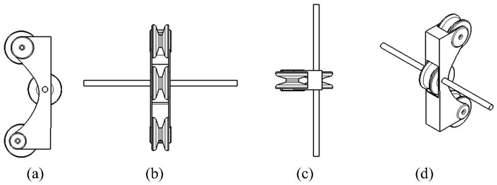

Embodiment Construction

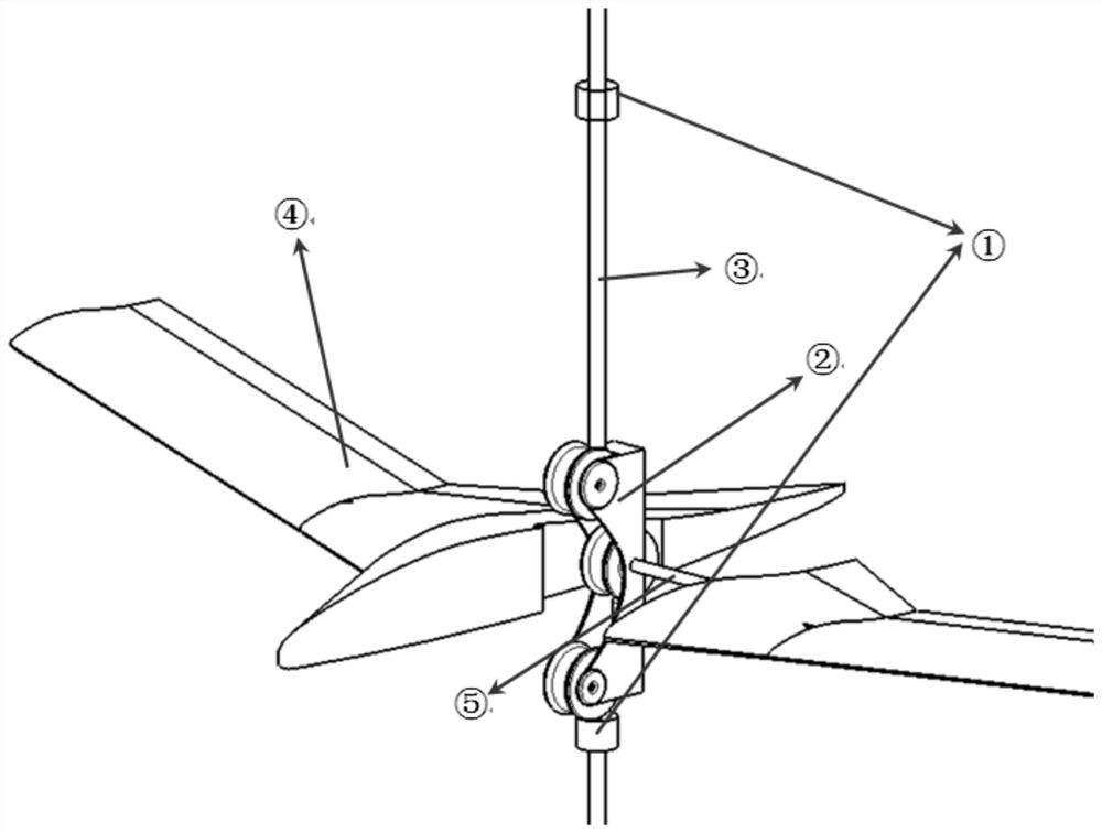
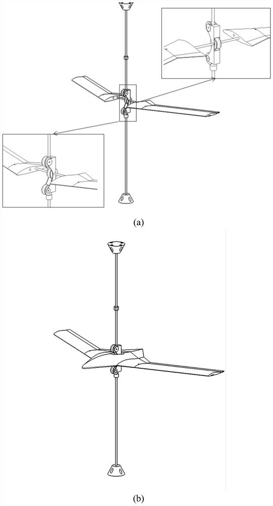
[0025] The invention proposes a supporting device in a full-span flying wing body degree of freedom fluttering wind tunnel test, which includes a beam, a pulley block and a steel shaft.

[0026] At the centroid of the flying wing, the model and the pulley block are connected by a beam (carbon fiber tube). The beam and the pulley block are connected by bearings to ensure that the relative rotation of the pulley block and the beam is not affected. The purpose is to release the flying wing during the experiment. Pitch degrees of freedom.

[0027] The pulley block includes a box body and three pulleys installed in the box body. The beam and the middle pulley in the pulley block are connected by bearings, and the other two pulleys are arranged on both sides of the middle pulley. Each pulley is in contact with the steel shaft, so that the pulley block can slide up and down on the steel shaft (or steel wire) stably, thereby releasing the degree of freedom of the model's ups and downs...


PUM


Abstract

The invention proposes a free-flying supporting device in a full-span flying-wing body degree-of-freedom fluttering wind tunnel test, which includes a beam, a pulley block and a steel shaft. The flying wing model is connected to the pulley block through the beam, and the bearing is connected between the beam and the pulley block to ensure that the relative rotation of the pulley block and the beam is not affected. The degree of freedom of the model's ups and downs, and a displacement limiter are also set up to limit the up and down movement of the model and prevent the model from being damaged due to divergence or severe oscillation. The invention adopts beams to connect the flying wing and the pulley block, which reduces the frictional resistance, does not need to design a separate support spring, and can release the degrees of freedom of ups and downs and pitches at the same time, has the advantage of being easy to implement, and avoids the impact of the support stiffness introduced by the support spring on the experimental results. influence; the designed supporting device can simulate the real flying state of the flying wing to the greatest extent, and can reduce the experimental error caused by frictional resistance.

Description

technical field [0001] The invention belongs to the technical field of fluttering wind tunnel test of flying wing body degree of freedom, in particular to a free-flying support device in full-span flying wing body degree of freedom fluttering wind tunnel test. Background technique [0002] The body degree of freedom flutter of a flying wing is a special kind of aeroelastic dynamic instability phenomenon caused by the coupling of the free rigid body pitching mode of the flying wing and the bending mode of the symmetrical wing. In the ground vibration test and wind tunnel test of the flutter model of the flying wing body degree of freedom, most of the research in recent years is mainly based on the half-span model, and the model suspension generally adopts the pitch / heave elastic support design with a balance weight method, this support method can realize the decoupling of the pitch / heave suspension support stiffness, but it cannot be directly used for the suspension of the fu...

Claims


Application Information

Patent Timeline
Patent Type & Authority Patents(China)
IPC IPC(8): G01M9/04
CPCG01M9/04
Inventor 谷迎松石鹏涛刘基海杨智春
Owner NORTHWESTERN POLYTECHNICAL UNIV
Learn More