Macrobend loss testing device for optical fiber automatic winding counting and test nethod thereof

A technology of winding device and testing device, which is used in measurement devices, optical instrument testing, and testing of machine/structural components, etc., can solve the problems of non-adjustable fiber spacing, difficult adjustment, affecting test results, etc., to improve accuracy and applicability. Wide range of effects for easy replacement

Pending Publication Date: 2020-01-14
CHENGDU TAIRUI COMM EQUIP DETECTION
View PDF0 Cites 7 Cited by
  • Summary
  • Abstract
  • Description
  • Claims
  • Application Information

AI Technical Summary

Problems solved by technology

For some types of optical fibers, the number of winding turns is less, and manual operation is a little easier, but for some types of optical fibers, the number of winding turns required reaches hundreds or even more, and manual winding makes the entire test efficiency lower;
[0007] 2) The wound optical fiber is always under stress, and the macrobending loss tested in the stressed state cannot truly reflect the macrobending loss characteristics of the optical fiber itself;
[0008] 3) It is not intuitive to read the number of winding turns of the optical fiber. Some winding devices may design circular grooves on the shaft, so that the optical f...

Method used


Image

  • Macrobend loss testing device for optical fiber automatic winding counting and test nethod thereof
  • Macrobend loss testing device for optical fiber automatic winding counting and test nethod thereof
  • Macrobend loss testing device for optical fiber automatic winding counting and test nethod thereof

Examples


Embodiment 1

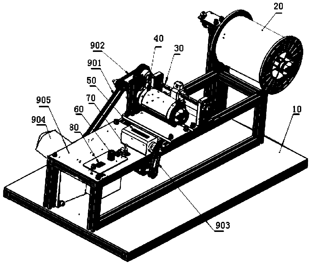
[0036] refer to figure 1 As shown, this embodiment discloses a macrobending loss testing device for optical fiber automatic winding counting, including a frame 10, an optical fiber reel pay-off device 20, a cable arrangement device 30, an optical fiber winding device 40, a counter 50 and a motor. The frame 10 is located below the entire device to support the entire winding device. The optical fiber reel pay-off device 20, the cable arrangement device 30, and the optical fiber winding device 40 are sequentially arranged on the frame. The optical fiber reel pay-off device 20 (the pay-off device is provided with a tensioning device, the purpose is to adjust the fiber optic reel pay-off tension or pay-off speed, and this device is applicable to large and small optical fiber reels) is located on the left side of the frame 10, and the cable arrangement device 20 has a wire The fiber guide hole 301 is set on the screw rod, and the optical fiber emitted by the fiber reel pay-off devic...

Embodiment 2

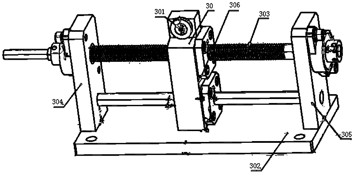
[0041] On the basis of Embodiment 1, the above-mentioned cable arranging device 30 includes: the above-mentioned cable arranging device bottom plate 302 , and the above-mentioned cable arranging device bottom plate 302 is used to support the above-mentioned cable arranging device 30 . The first support 304 of the cable arrangement device and the second support 305 of the cable arrangement device are arranged on both sides of the bottom plate 302 of the cable arrangement device. The part between the first support 304 of the above-mentioned cable arrangement device and the second support 305 of the above-mentioned cable arrangement device is also provided with the third support 306 of the above-mentioned cable arrangement device, and the top of the third support 306 of the above-mentioned cable arrangement device is equipped with a fiber guide hole 301, the fiber guide hole 301 is made of brass, the first function of the fiber guide hole is to protect the optical fiber, and the s...

Embodiment 3

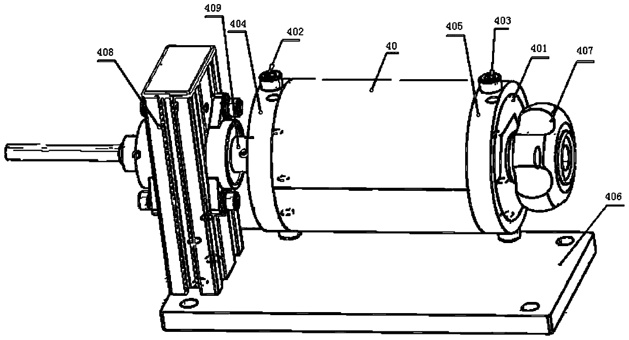
[0044] On the basis of Embodiment 1, the optical fiber winding device 40 includes: a bottom plate 406 of the optical fiber winding device, and the bottom plate 406 of the optical fiber winding device is used to support the optical fiber winding device 40 . The optical fiber winding device base plate 406 left side is provided with the optical fiber winding device support 408, and the optical fiber winding device support 408 is provided with the fixed-diameter shaft support shaft 409 that is placed parallel to the optical fiber winding device base plate 406, and the above-mentioned fixed-diameter shaft support shaft 409 is used to support the above-mentioned The fixed diameter shaft 401 of the optical fiber winder 40 is fixed by the fixed diameter shaft locking device 407 . Half of the fixed diameter shaft 401 is fixed, and the other half of the fixed diameter shaft 401 is loose, the interface between the fixed part and the loose part is parallel to the axial direction, and the t...


PUM


Abstract

The invention relates to the field of optical fiber manufacturing detection and discloses a macrobend loss testing device for optical fiber automatic winding counting. An optical fiber disc pay-off device, a line arrangement device and an optical fiber winding device are sequentially arranged on a rack; the line arrangement device is provided with a lead screw; a fiber guide hole is formed in thelead screw; and an optical fiber paid off by the optical fiber disc pay-off device passes through the fiber guide hole and is pulled to the optical fiber winding device; the optical fiber winding device is provided with a diameter fine adjustment unit; a motor rotating shaft drives an optical fiber winding device rotating shaft through a belt wheel; the optical fiber winding device rotating shaftdrives the lead screw of the line arrangement device to rotate through the belt wheel; and the optical fiber winding device rotating shaft drives an optical fiber winding counter rotating shaft through the belt wheel. Through the structure, after the number of turns of winding reaches the standard requirement, the shaft diameter fine adjustment device is loosened, so that the optical fiber meetingthe standard requirement is not stressed after being wound, and the accuracy of an optical fiber macrobend loss test result is improved. Meanwhile, the invention further discloses a test method of the device.

Description

technical field [0001] The invention relates to the field of optical fiber manufacturing and testing, in particular to a macrobending loss testing device and a testing method for optical fiber automatic winding counting. Background technique [0002] With the acceleration of the commercialization of 400G systems, the issuance of 5G licenses, and the rapid acceleration of 5G deployment, the application of 5G will be accompanied by higher requirements for high transmission rate, large capacity, and long-distance transmission, and higher requirements for fiber attenuation. The higher and higher the requirements for the reliability of communication are getting higher and higher. Optical fiber is considered to be the best transmission medium for high-bandwidth and long-distance transmission. One of the key factors to realize these functions is that optical fiber has very low loss, and optical power loss is a very important determinant of network performance. [0003] The loss ma...

Claims


Application Information

Patent Timeline
IPC IPC(8): G01M11/00
CPCG01M11/00
Inventor 左琼华李吉超杨先金宋志佗甘露时彬孔超
Owner CHENGDU TAIRUI COMM EQUIP DETECTION
Why Eureka
Try Eureka