High-heat-flux electronic component constant-temperature liquid cooling plate

A technology of high heat flux density and electronic components, applied in electrical components, circuits, secondary batteries, etc., can solve the problems of easy leakage of welding seam, corrosion leakage, heavy weight, etc.

Active Publication Date: 2020-01-14
付香花
View PDF4 Cites 5 Cited by
  • Summary
  • Abstract
  • Description
  • Claims
  • Application Information

AI Technical Summary

Problems solved by technology

[0006] 2) When the heat flux is high, the temperature rise suppression performance of the liquid cold plate is poor
Although such a liquid-cooled plate solves the problem of "small heat dissipation area, weak rigidity, complicated assembly, and easy leakage of weld seam after long-term use", the production of such a structural aluminum material requires a special extrusion die, which is costly and relatively heavy. Heavy, the one-piece extruded aluminum also has a weld seam with the side solid plate, and the weld seam will also corrode the leakage after long-term use

Method used


Image

  • High-heat-flux electronic component constant-temperature liquid cooling plate
  • High-heat-flux electronic component constant-temperature liquid cooling plate
  • High-heat-flux electronic component constant-temperature liquid cooling plate

Examples


Embodiment 1

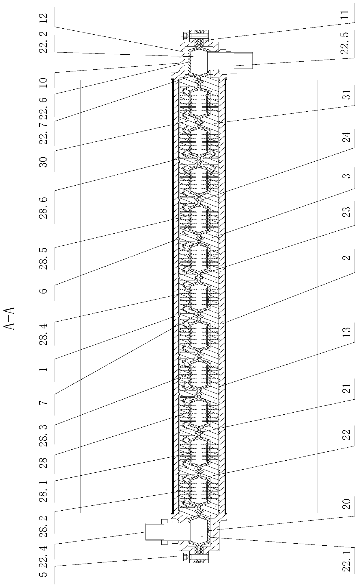
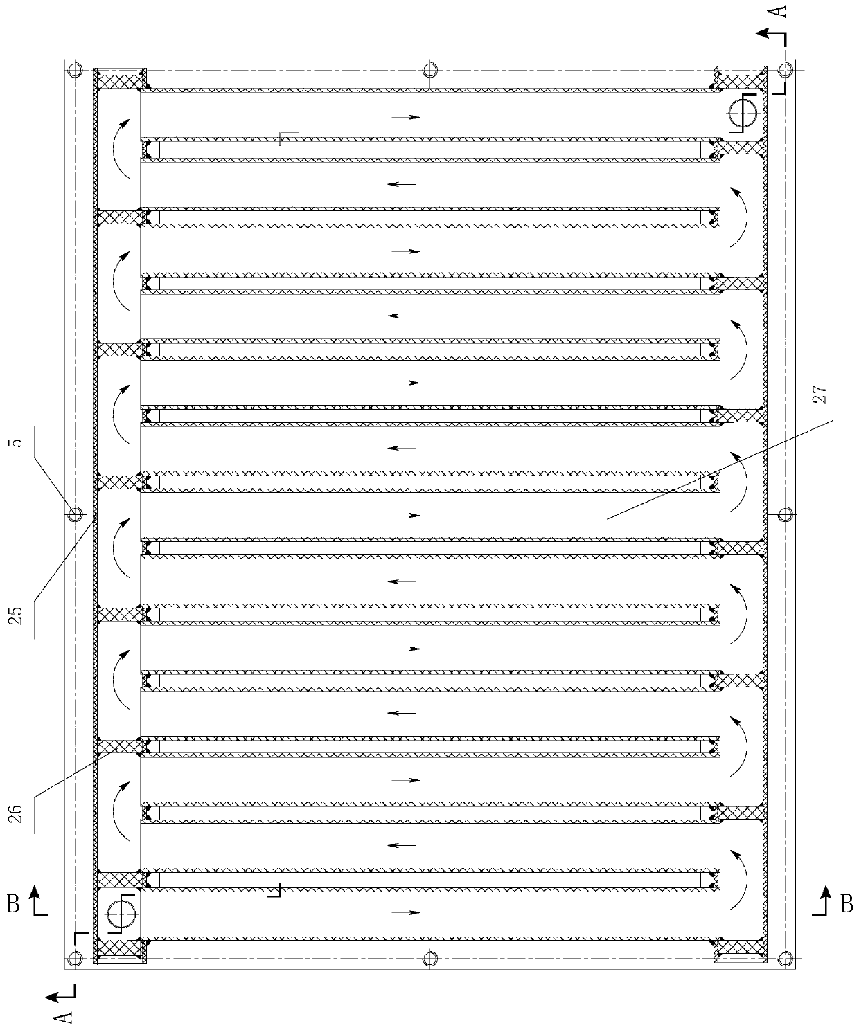
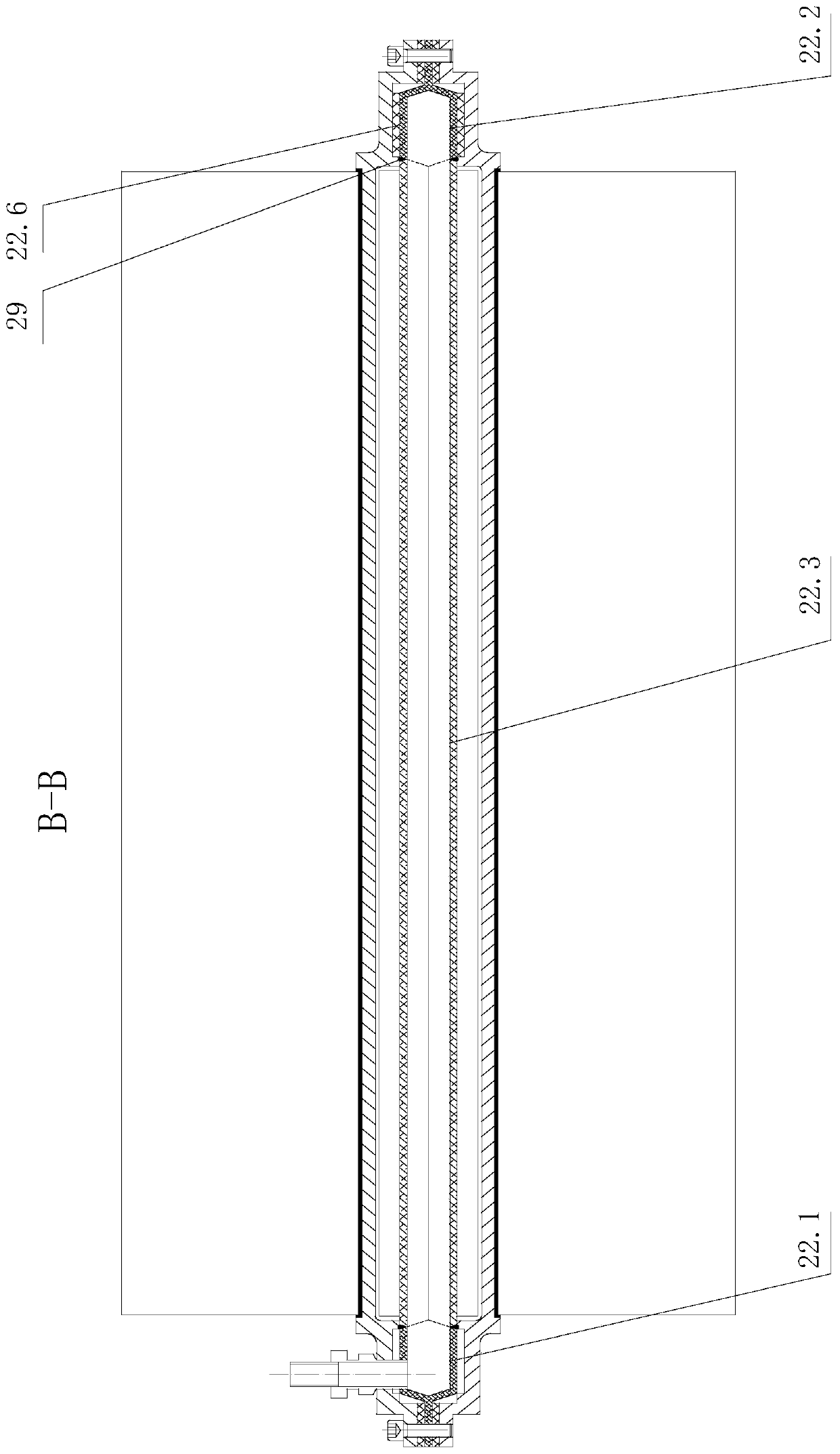
[0044] Such as Figure 1-3 As shown, a high heat flux constant temperature liquid cold plate for electronic components includes an upper cold plate 1, a liquid cooling mechanism 20 and a lower cold plate 2 stacked in sequence, and the upper cold plate 1 and the lower cold plate 2 respectively have a buckle sealing mechanism 10 The buckle sealing mechanism 10 includes a buckle flange part 11, a pressure flange part 12 and a concave cavity 13, and the upper cold plate 1 and the lower cold plate 2 are fastened to the liquid cooling mechanism through the buckle flange part 11 and the sealing ring respectively. 20 and tightened by the compression bolt 5, the pressure flange part 12 is pressed against the liquid cooling mechanism 20 through the sealing ring, so that the concave cavity of the upper cold plate and the concave cavity of the lower cold plate are combined to form a liquid-cooled The constant temperature chamber 3 on both sides of the mechanism 20 is provided with a solid...


PUM


Abstract

A high-heat-flux electronic component constant-temperature liquid cooling plate comprises an upper cooling plate, a liquid cooling mechanism and a lower cooling plate which are stacked in sequence, after stacking, a concave cavity of the upper cooling plate and a concave cavity of the lower cooling plate are oppositely combined to form a constant-temperature cavity surrounding the two sides of theliquid cooling mechanism, and a solid-liquid phase change heat storage mechanism is arranged in the constant-temperature cavity; the liquid cooling mechanism comprises a liquid cooling plate body anda connecting pipe body, the liquid cooling plate body comprises multiple paths of parallel pipe body parts, the head ends and the tail ends of the pipe body parts penetrate the connecting pipe body and are integrally welded, and the connecting pipe body is provided with multiple plugs at intervals, so that the multiple paths of parallel pipe body parts communicate end to end to form an S-shaped cooling path; and the solid-liquid phase change heat storage mechanism comprises a solid-liquid phase change heat storage material which is in gapless direct contact with the inner wall of the concavecavity in a solid state or a liquid state. The high-heat-flux electronic component constant-temperature liquid cooling plate can keep the long-term temperature of a power battery below the melting point of a solid-liquid phase change material, the temperature rise rate is low, and the temperature difference of all parts is small.

Description

technical field [0001] The invention relates to the technical field of heat dissipation of electronic components, in particular to a constant temperature liquid cooling plate for high heat flux density electronic components. Background technique [0002] Since the advent of the transistor in 1947, electronic components have developed rapidly, and more and more power and smaller and smaller volumes are the trend. This high level of integration has resulted in a large number of high heat flux electronic devices. Excessive junction temperature of electronic devices with high heat flux will lead to failure of electronic devices. When the operating temperature increases by 2°C, the reliability will decrease by 10%. Therefore, the reliability of electronic equipment with high heat flux needs to be guaranteed by cooling technology. The so-called high heat flux refers to the heat flux greater than or equal to 100W / cm 2 . For example, take a high-performance multi-core CPU as an ...

Claims


Application Information

Patent Timeline
Patent Type & Authority Applications(China)
IPC IPC(8): H01M10/613H01M10/653H01M10/6551H01M10/6554H01M10/6556H01M10/6567H01M10/656H01M10/635
CPCH01M10/613H01M10/635H01M10/653H01M10/6551H01M10/6554H01M10/6556H01M10/656H01M10/6567Y02E60/10
Inventor 潘洪建
Owner 付香花
Why Eureka
Try Eureka