
Setting machine flue gas treatment device

A technology for flue gas treatment and setting machine, which is applied in gas treatment, transportation and packaging, and dispersed particle filtration, etc. It can solve the problem of affecting the work efficiency of maintenance personnel, the activated carbon filter plate cannot be quickly disassembled, and the overall flue gas treatment of the setting machine cannot be normal Operation and other issues, to achieve the effect of safe and convenient use, scientific and reasonable structure

Inactive Publication Date: 2020-01-17
湖州荣大环境科技有限公司
View PDF0 Cites 1 Cited by
  • Summary
  • Abstract
  • Description
  • Claims
  • Application Information

AI Technical Summary

Problems solved by technology

[0003] The object of the present invention is to provide a kind of fume treatment device of setting machine, to solve the above-mentioned background technology, although the existing fume treatment device can filter the setting machine, there are existing setting machine fume treatment steps. When the utilization rate of the activated carbon plate in the activated carbon adsorption device reaches saturation, the activated carbon plate needs to be replaced. The activated carbon filter plate in the existing activated carbon adsorption device cannot be quickly disassembled, which not only affects the work efficiency of maintenance personnel, but also causes stereotyped machine smoke The gas treatment as a whole cannot operate normally

Method used

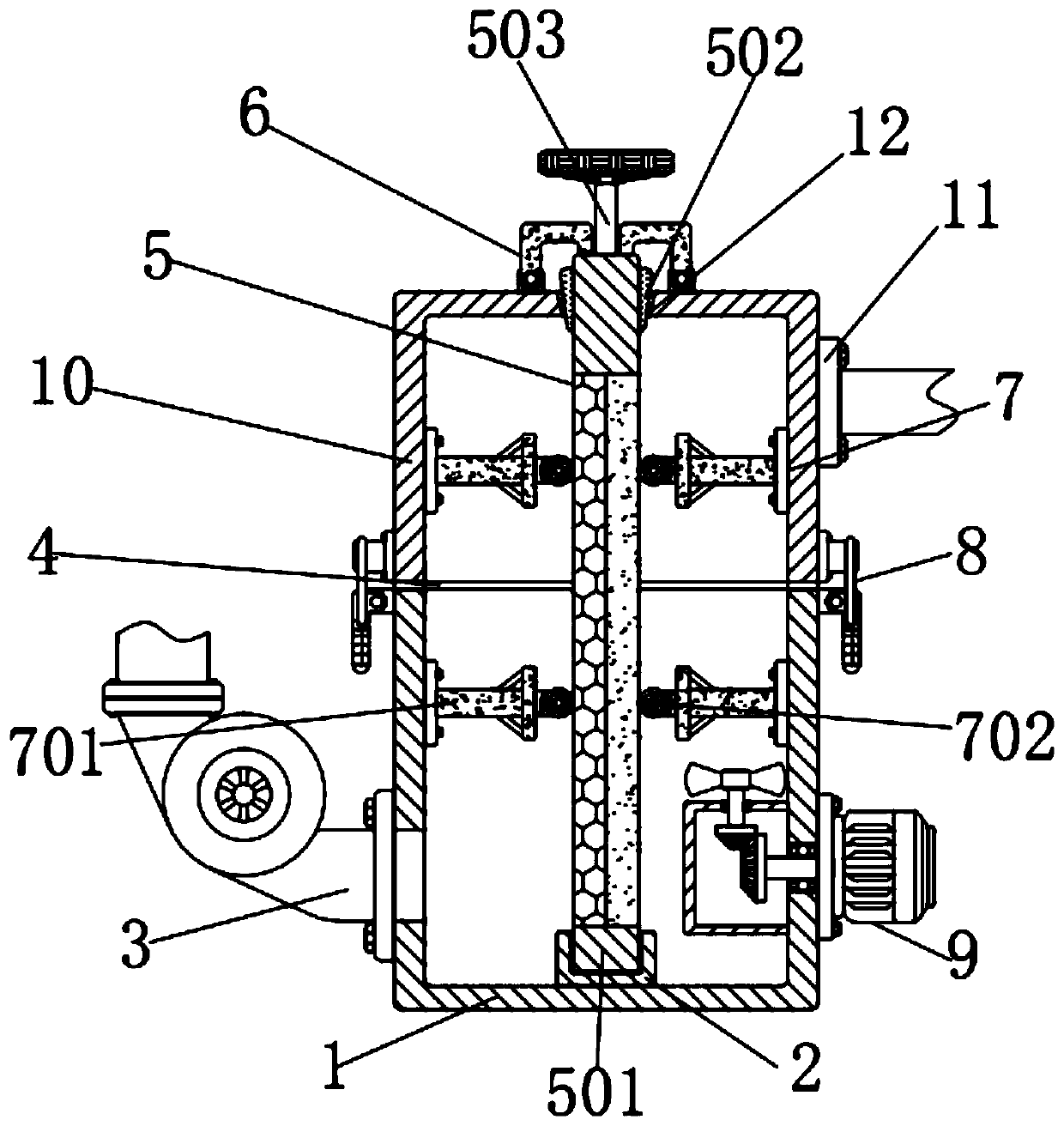
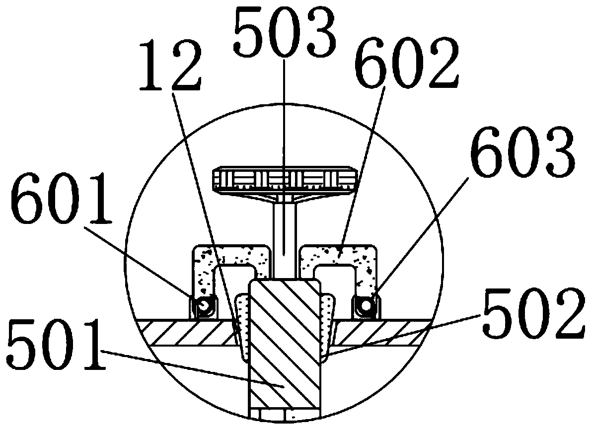
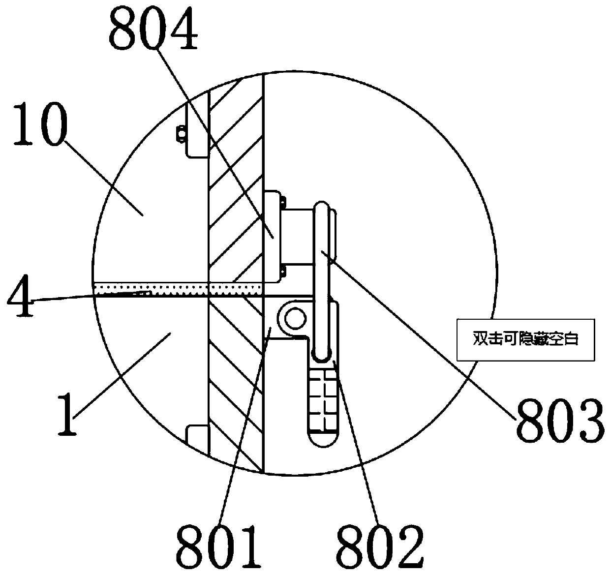

Image

  • Setting machine flue gas treatment device
  • Setting machine flue gas treatment device
  • Setting machine flue gas treatment device

Examples


Embodiment Construction

[0028] The following will clearly and completely describe the technical solutions in the embodiments of the present invention with reference to the accompanying drawings in the embodiments of the present invention. Obviously, the described embodiments are only some, not all, embodiments of the present invention. Based on the embodiments of the present invention, all other embodiments obtained by persons of ordinary skill in the art without making creative efforts belong to the protection scope of the present invention. see Figure 1-4 , the present invention provides a technical solution: a flue gas treatment device for a setting machine, including a lower box 1 and an upper box 10, a groove block 2 is fixedly connected to the bottom of the inner wall of the lower box 1, and the left side of the lower box 1 The side is connected with an exhaust fan 3. The model of the exhaust fan 3 is 1.1KW-2P-2. The exhaust fan 3 is used to pour the flue gas into the interior of the upper box...


PUM


Abstract

The invention discloses a setting machine flue gas treatment device. The setting machine flue gas treatment device comprises a lower box body and an upper box body, a groove block is fixedly connectedto the bottom of the inner wall of the lower box body; a filter plate is in clearance fit with the inner wall of a box body opening, the outer wall of the top of the filter plate is sleeved with a rubber plug, the outer wall of the rubber plug is in interference fit with the inner wall of the box body opening, the bottom of the filter plate is in clearance fit with the inner wall of a groove of the groove block, and the top of the filter plate is fixedly connected with a handle. According to the setting machine flue gas treatment device, the filter plate, the rubber plug and the box body opening are matched; activated carbon plates should be replaced; through cooperation between a support and rolling wheels, when the filter plate is installed, rapid positioning can be conducted, and the problems that the filter plate cannot be vertically and fixedly installed, and consequently the effect is poor when the filter plate is used for filtering flue gas is solved.

Description

technical field [0001] The invention relates to the technical field of flue gas treatment, in particular to a flue gas treatment device for a setting machine. Background technique [0002] The textile printing and dyeing industry sizing machine exhaust gas treatment project is a multi-benefit project. After the project is implemented, it can produce long-term social benefits in terms of improving the quality of the community environment and improving the working environment of the workshop. At the same time, through the implementation of the exhaust gas treatment project, the waste oil in the flue gas can be recovered, which can generate certain economic benefits. Although the existing flue gas treatment device can filter the sizing machine, there are existing sizing machine flue gas treatment steps When the utilization rate of the activated carbon plate in the activated carbon adsorption device reaches saturation, the activated carbon plate needs to be replaced. The activat...

Claims


Application Information

Patent Timeline
Patent Type & Authority Applications(China)
IPC IPC(8): B01D46/00B01D46/10B01D53/04B01D53/88
CPCB01D46/0039B01D46/0027B01D46/0036B01D46/10B01D53/0407B01D53/0446B01D53/885B01D2253/102B01D2255/20707B01D2258/0283B01D46/88
Inventor 徐永杰
Owner 湖州荣大环境科技有限公司
Learn More