Chemical new material uniform mixing device

A new material and mixing technology, applied in mixers, metal processing, chemical instruments and methods, etc., can solve the problems of easy agglomeration, incomplete mixing, etc., and achieve the effect of mixing evenly

Inactive Publication Date: 2020-01-17
黄水泉
0 Cites 4 Cited by

AI-Extracted Technical Summary

Problems solved by technology

[0003] When mixing chemical materials with a powdery structure, the material located between the inner wall of the mixing tank and the end of the stirring shaft is often not stirred, which will cause uniform mixing in the middle, and the...

Method used

As shown in Figure 6, described telescopic device 16 is made up of housing b1, coil spring b2, fixed shaft b3, and described housing b1 is provided with coil spring b2 and fixed shaft b3, and describ...

Abstract

The invention discloses a chemical new material uniform mixing device which structurally comprises a frame, a stirring barrel, a feeding hole, a discharging hole, a motor, a speed reducer and a coupling, wherein the stirring barrel is mounted on the right side of the top of the frame; the feeding hole is formed in the right side of the top of the stirring barrel; the discharging hole is formed under the feeding hole; the motor is mounted on the left side of the stirring barrel; the motor is connected with the speed reducer; and the motor is connected with the stirring barrel through the coupling. The chemical new material uniform mixing device has the beneficial effects that a scraper is mounted at the tail end of a stirring shaft, under the action of centrifugal force, a scraper plate onthe scraper is unfolded outwards and is attached to the inner wall of the stirring barrel to scrape materials attached to the inner wall, and stirring is performed; conical teeth are arranged on a rolling brush and can crush agglomerated materials to be scattered in the stirring shaft for stirring; and a coil spring is arranged in a fixed disk and can enable steel wires to be in a tight state, andthe steel wires cut the agglomerated materials, so that stirring is more uniform.

Application Domain

Rotary stirring mixersTransportation and packaging +4

Technology Topic

PhysicsCoil spring +5

Image

  • Chemical new material uniform mixing device
  • Chemical new material uniform mixing device
  • Chemical new material uniform mixing device

Examples

  • Experimental program(1)

Example Embodiment

[0027] In order to make the technical means, creative features, objectives and effects of the present invention easy to understand, the present invention will be further explained below in conjunction with specific embodiments.
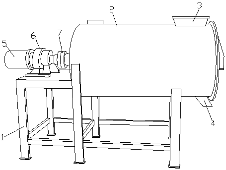
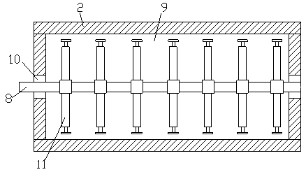
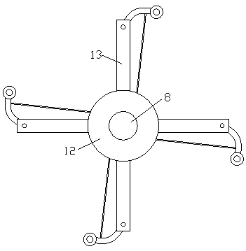
[0028] See Figure 1-Figure 6 , The present invention provides a technical solution for a new chemical material mixing equipment:
[0029] Such as figure 1 with figure 2 As shown, the structure includes a frame 1, a mixing barrel 2, a material inlet 3, a material outlet 4, a motor 5, a reducer 6, and a coupling 7. A mixing barrel is installed on the right side of the top of the frame 1 2. A feed port 3 is provided on the right side of the top of the mixing tank 2, a discharge port 4 is provided directly below the feed port 3, and the motor 5 is installed on the left side of the mixing tank 2. The motor 5 is connected to the reducer 6, and the motor 5 is connected to the mixing tank 2 through a coupling 7;
[0030] Wherein, a rotating shaft 8 is installed in the inner cavity 9 of the mixing tank 2, and the rotating shaft 8 penetrates the mixing tank 2, and bearings 10 are installed in the middle of the left and right sides of the mixing tank 2. The rotating shaft 8 and the bearing 10, the rotating shaft 8 is equipped with more than two sets of stirring devices 11 evenly and equidistantly. The material is added from the feed port 3 to the inner cavity 9 of the mixing barrel 2, and the motor 5 drives the stirring on the rotating shaft 8. The device 11 stirs and mixes the materials.
[0031] Such as image 3 with Figure 4 As shown, the stirring device 11 is composed of a fixed plate 12, a stirring shaft 13, a side scraper 14, a steel wire 15, and a retractor 16. The fixed plate 12 is provided with four sets of stirring shafts 13 evenly and equidistantly. , The end of the stirring shaft 13 is hinged with a side scraper 14 which is connected to the retractor 16 inside the fixed plate 12 through a steel wire 15 and the scraper 14 is opposite to the inner cavity 9 The material on the inner wall is scraped off and stirred.
[0032] Such as Figure 5 As shown, the side scraper 14 is composed of a scraper a1, a rotating column a2, a hinge shaft a3, a roller brush holder a4, and a roller brush a5. The scraper a1 is provided with a rotating column a2 on the left side and connected on the right side. There is a roller brush holder a4, a hinge shaft a3 is connected to the rotating column a2, and a roller brush a5 is installed on the roller brush holder a4. The roller brush a5 scrapes the material attached to the inner wall along the rotation direction of the stirring shaft 13 .
[0033] Such as image 3 As shown, the end of the stirring shaft 13 is provided with a U-shaped opening, and the rotating column a2 is hingedly connected to the through hole on the U-shaped opening through a hinge shaft a3.
[0034] Such as Figure 5 As shown, the right side of the roller brush holder a4 is provided with a groove through hole, the roller brush a5 is movably installed in the groove through hole, and the roller brush a5 is evenly provided with more than two bevel teeth e, Bevel teeth e can crush agglomerated materials.
[0035] Such as Image 6 As shown, the retractor 16 is composed of a housing b1, a coil spring b2, and a fixed shaft b3. The housing b1 is provided with a coil spring b2 and a fixed shaft b3. The coil spring b2 is fixed on the fixed shaft b3. The coil spring b2 is connected with the steel wire 15, and the tight steel wire 15 cuts the agglomerated material to make it more evenly mixed.
[0036] The material to be mixed is added from the feed port 3 into the inner cavity 9 of the mixing barrel 2, the motor 5 drives the stirring device 11 on the rotating shaft 8 to stir and mix the materials; the scraper 14 drives the stirring shaft 13 Under the centrifugal movement, the scraper a1 stretches the steel wire 15 in a taut state under the action of centrifugal force. At this time, the coil spring b2 is in a stretched state. The material is cut to make the mixing more uniform; at the same time, the rolling brush a5 on the scraper a1 scrapes the material attached to the inner wall, and the bevel tooth e on the rolling brush a5 can crush the agglomerated material; the end of the stirring After that, the coil spring b2 resets the scraper 14 through the steel wire 15, and the mixed material is poured out from the discharge port 4.
[0037] The foregoing only describes the basic principles and preferred embodiments of the present invention. Those skilled in the art can make many changes and improvements based on the above description, and these changes and improvements should fall within the protection scope of the present invention.
[0038] In addition, it should be understood that although this specification is described in accordance with the implementation manners, not each implementation manner only includes an independent technical solution. This narration in the specification is only for clarity, and those skilled in the art should consider the specification as a whole The technical solutions in the embodiments can also be appropriately combined to form other implementations that can be understood by those skilled in the art.

PUM

no PUM

Description & Claims & Application Information

We can also present the details of the Description, Claims and Application information to help users get a comprehensive understanding of the technical details of the patent, such as background art, summary of invention, brief description of drawings, description of embodiments, and other original content. On the other hand, users can also determine the specific scope of protection of the technology through the list of claims; as well as understand the changes in the life cycle of the technology with the presentation of the patent timeline. Login to view more.

Similar technology patents

Concrete stirring device

InactiveCN106042180AStir wellgood mixing effect
Owner:刘继宏

Stirring device for honey production

InactiveCN108294271Aeasy to stirStir well
Owner:湖州语纳蜂产品有限公司

Stirring machine

Owner:深圳市能迩环保科技实业发展有限公司

Paper pulp stirring device for papermaking

Owner:平阳县恒信印业有限公司

Classification and recommendation of technical efficacy words

  • Stir well

Chemical raw material stirring and drying device

InactiveCN107983248AIncrease the stirring areastir well
Owner:长沙德科投资管理咨询有限公司

Uniform-stirring adhesive stirring device

InactiveCN106732079Awell mixedStir well
Owner:WUXI HITXINCHENG POLYMER TECH
Why Eureka
Try Eureka